
Explorer 2WD V6-4.0L (2009)
REPAIR the circuit. CONNECT the negative battery cable. CLEAR the DTCs. REPEAT the network test with the scan tool.
-------------------------------------------------
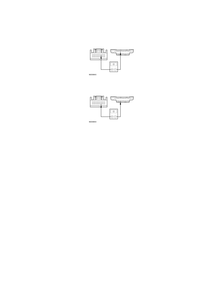
O7 CHECK THE MS-CAN CIRCUITS BETWEEN THE PAM AND THE DLC FOR AN OPEN (ULTRASONIC)
-
Measure the resistance between the PAM C4014-3 (Mountaineer) or C3267-3 (Explorer Sport Trac), circuit VDB06 (GY/OG), harness side and
the DLC C251-3, circuit VDB06 (GY/OG), harness side.
-
Measure the resistance between the PAM C4014-11 (Mountaineer) or C3267-11 (Explorer Sport Trac), circuit VDB07 (VT/OG), harness side and
the DLC C251-11, circuit VDB07 (VT/OG), harness side.
-
Are the resistances less than 5 ohms?
Yes
CONNECT the negative battery cable. GO to O8.
No
REPAIR the circuit in question. CONNECT the negative battery cable. CLEAR the DTCs. REPEAT the network test with the scan tool.
-------------------------------------------------
O8 CHECK FOR CORRECT PAM OPERATION
-
Disconnect the PAM connector.
-
Check for:
-
corrosion
-
damaged pins
-
pushed-out pins
-
Connect the PAM connector and make sure it seats correctly.
-
Operate the system and verify the concern is still present.
-
Is the concern still present?
Yes
INSTALL a new PAM. CLEAR the DTCs. REPEAT the network test with the scan tool.
No
The system is operating correctly at this time. The concern may have been caused by a loose or corroded connector. CLEAR the DTCs. REPEAT the
network test with the scan tool.
-------------------------------------------------
Pinpoint Test P: The Accessory Protocol Interface Module (APIM) Does Not Respond To The Scan
Tool
Communications Network