
Explorer 2WD V6-4.0L (2009)
test. See: Initial Inspection and Diagnostic Overview/Communications Network/Inspection And Verification
NOTE: Failure to disconnect the battery when instructed will result in false resistance readings. Refer to Battery.
-------------------------------------------------
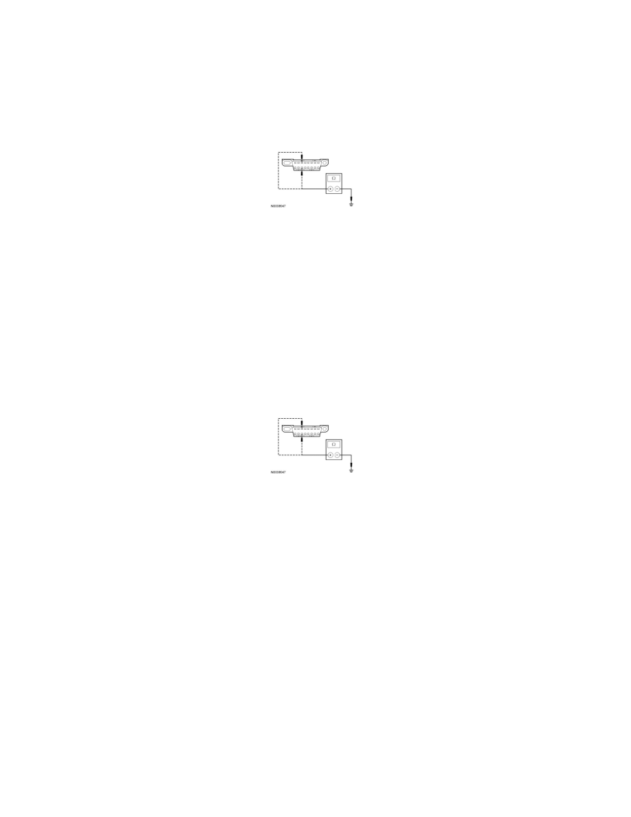
Q28 CHECK THE MS-CAN (+) AND MS-CAN (-) CIRCUITS FOR A SHORT TO GROUND WITH THE IC DISCONNECTED
-
Disconnect: ICC220.
-
Measure the resistance between the DLC C251-3, circuit VDB06 (GY/OG), harness side and ground; and between the DLC C251-11, circuit
VDB07 (VT/OG), harness side and ground.
-
Are the resistances greater than 1,000 ohms?
Yes
CONNECT the negative battery cable. GO to Q45.
No
GO to Q29.
-------------------------------------------------
Q29 CHECK THE MS-CAN (+) AND MS-CAN (-) CIRCUITS FOR A SHORT TO GROUND WITH THE ACM DISCONNECTED
-
Disconnect: ACM C290b.
-
Measure the resistance between the DLC C251-3, circuit VDB06 (GY/OG), harness side and ground; and between the DLC C251-11, circuit
VDB07 (VT/OG), harness side and ground.
-
Are the resistances greater than 1,000 ohms?
Yes
CONNECT the negative battery cable. GO to Q46.
No
GO to Q30.
-------------------------------------------------
Q30 VERIFY VEHICLE EQUIPMENT - HVAC MODULE
-
Inspect the vehicle for an HVAC module.
-
Is the vehicle equipped with an HVAC module?
Yes
GO to Q31.
No
GO to Q32.
-------------------------------------------------
Q31 CHECK THE MS-CAN (+) AND MS-CAN (-) CIRCUITS FOR A SHORT TO GROUND WITH THE HVAC MODULE