
Explorer 2WD V6-4.0L (2009)
-
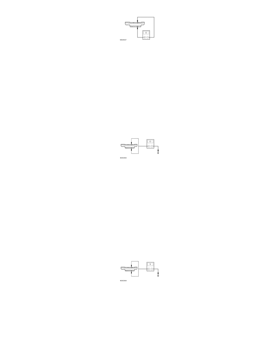
Is the resistance between 54 and 66 ohms?
Yes
GO to T3.
No
CONNECT the negative battery cable. Go To Pinpoint Test R. See: Pinpoint Test R: Intermittent No Medium Speed Controller Area Network
(MS-CAN) Communication, One Or More Modules Are Not Respo
-------------------------------------------------
T3 CHECK THE HS-CAN (+) AND HS-CAN (-) CIRCUITS FOR A SHORT TO GROUND
-
Measure the resistance between the DLC C251-6, circuit VDB04 (WH/BU), harness side and ground; and between the DLC C251-14, circuit
VDB05 (WH), harness side and ground.
-
Are the resistances greater than 1,000 ohms?
Yes
CONNECT the negative battery cable. GO to T4.
No
CONNECT the negative battery cable. Go To Pinpoint Test R. See: Pinpoint Test R: Intermittent No Medium Speed Controller Area Network
(MS-CAN) Communication, One Or More Modules Are Not Respo
-------------------------------------------------
T4 CHECK THE HS-CAN (+) AND HS-CAN (-) CIRCUITS FOR A SHORT TO VOLTAGE
-
Ignition ON.
-
Measure the voltage between the DLC C251-6, circuit VDB04 (WH/BU), harness side and ground; and between the DLC C251-14, circuit
VDB05 (WH), harness side and ground.
-
Are the voltages greater than 6 volts?
Yes
REPAIR the circuit in question. CLEAR the DTCs. REPEAT the network test with the scan tool.
No
GO to T5.
-------------------------------------------------
T5 CHECK FOR RESTORED COMMUNICATION WITH THE PCM DISABLED