
Explorer 2WD V8-4.6L (2008)
Removal
1. NOTE: If equipped with adjustable pedals, when removing the adjustable pedal assembly, make sure the pedals are adjusted to the full forward
position.
Depower the supplemental restraint system (SRS). For additional information, refer to Air Bag Systems.
2. CAUTION: Do not service the brake pedal without first removing the stoplamp switch and speed control deactivator switch. These
switches must be removed with the brake pedal in the at-rest position. Switch plungers must be compressed for the switch to rotate in the
bracket. Attempting to remove the switch when the plunger is extended (during pedal apply) will result in damage to the switch.
Remove the stoplamp switch. For additional information, refer to Lighting and Horns.
3. Remove the speed control deactivator switch.
For additional information, refer to Cruise Control.
4. NOTE: The booster push rod clevis locking pin is a one-time use only part. Anytime the booster push rod clevis locking pin is removed, a new
booster push rod clevis locking pin should be used.
NOTE: Remove the clevis locking pin by squeezing the locking tabs and pulling outward on the opposite end.
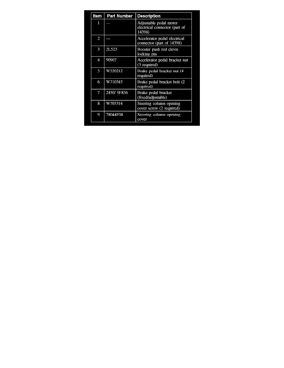
Remove the booster push rod clevis locking pin and discard.
5. Disconnect the brake booster rod from the brake pedal and position aside.
6. If equipped with power adjustable pedals, disconnect the adjustable pedal motor electrical connector.
7. If equipped with adjustable pedals, disconnect the accelerator pedal motor electrical connector.
8. Remove and discard the 2 brake pedal bracket bolts.
9. Remove and discard the 4 brake booster nuts.
10. Position the brake master cylinder and brake booster assembly forward to allow the brake pedal assembly to clear the studs.
11. Remove the 3 accelerator pedal bracket nuts.
12. Remove the 2 steering column opening cover screws and the steering column opening cover panel.
13. CAUTION: Do not allow the steering wheel to rotate while the steering column intermediate shaft is disconnected or damage to the
clockspring can result. If there is evidence the steering column shaft has rotated, the clockspring must be removed and centered. For
additional information, refer to Air Bag Systems.
Secure the steering wheel using a suitable holding device.
14. Remove the steering column shaft bolt and disconnect the steering column shaft from the steering column.
15. Remove the brake pedal assembly from the vehicle.
Installation
1. Position the brake pedal assembly in the vehicle.
2. Position the brake master cylinder and brake booster assembly into the brake pedal bracket assembly.
3. Install the 4 new brake booster nuts.
^
Tighten to 22 Nm (16 lb-ft).