
Explorer 2WD V8-4.6L (2008)
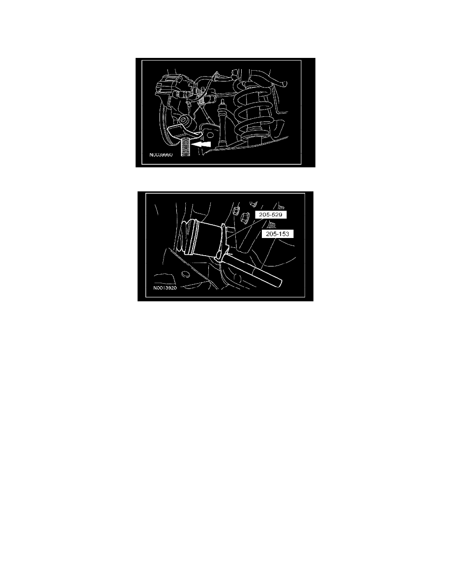
9. Pivot the wheel knuckle assembly upward on the upper arm outboard bolt.
^
Loosen the upper arm bolt to prevent bushing damage.
^
To install, tighten to 275 Nm (203 lb-ft) at curb ride height.
10. Using the special tool, disengage the inboard CV joint housing from the differential side gear.
11. Remove the halfshaft assembly.
12. CAUTION: Do not tighten the rear wheel hub nut with the vehicle on the ground. The nut must be tightened to specification before the
vehicle is lowered onto the wheels. Wheel bearing damage will occur if the wheel bearing is loaded with the weight of the vehicle applied.
NOTE: Install and tighten the new axle wheel end nut to specification in a continuous rotation. Stopping the rotation during installation will cause
the nylon lock to seat incorrectly. This will cause incorrect torque readings while tightening the axle wheel end nut and lead to bearing failure.
Always install a new axle wheel end nut, after loosening or when not tightened to specifications, in a continuous rotation.
NOTE: Always install a new differential stub shaft seal whenever the halfshaft is removed.
NOTE: Make sure the halfshaft is completely seated in the differential side gear by pushing the halfshaft into the rear axle assembly until an
audible click is heard or a leak may occur from the axle assembly.
NOTE: Apply the brake to keep the halfshaft from rotating.
To install, reverse the removal procedure.