
Explorer 4WD V6-4.0L (2009)
16. Remove the 2 inboard and 2 outboard latch-to-backrest frame bolts.
17. Remove the 60 percent backrest.
-
For Explorer and Mountaineer, position the latch release cable out from between the backrest frame and backrest support panel.
Installation
Sport Trac vehicles
1. Install the backrest frame to the inboard and outboard latches in the following sequence.
1. Position the backrest frame to the inboard and outboard latches and hand-start the 2 inboard and 2 outboard latch-to-backrest frame bolts.
2. Hand-start the outboard upper pivot latch bolt.
3. Install the 2 inboard latch-to-backrest frame bolts.
-
Tighten to 40 Nm (30 lb-ft).
4. Install the 2 outboard latch-to-backrest frame bolts.
-
Tighten to 40 Nm (30 lb-ft).
5. Install the outboard upper pivot latch bolt.
-
Tighten to 40 Nm (30 lb-ft).
2. Position the upper latch and install the bolts.
-
Tighten to 25 Nm (18 lb-ft).
3. Position the inner latch cover and install the screw.
4. NOTE: The safety belt retractor has been removed for clarity.
Position the backrest support panel to the backrest frame and route the latch release cable.
-
The latch release cable is to pass between the backrest frame and the backrest support at the 2 points shown.
5. NOTE: The cable is to move freely after assembly.
Install the backrest support panel screws to the backrest frame.
-
Attach the latch release cable to the backrest support panel.
Explorer and Mountaineer vehicles
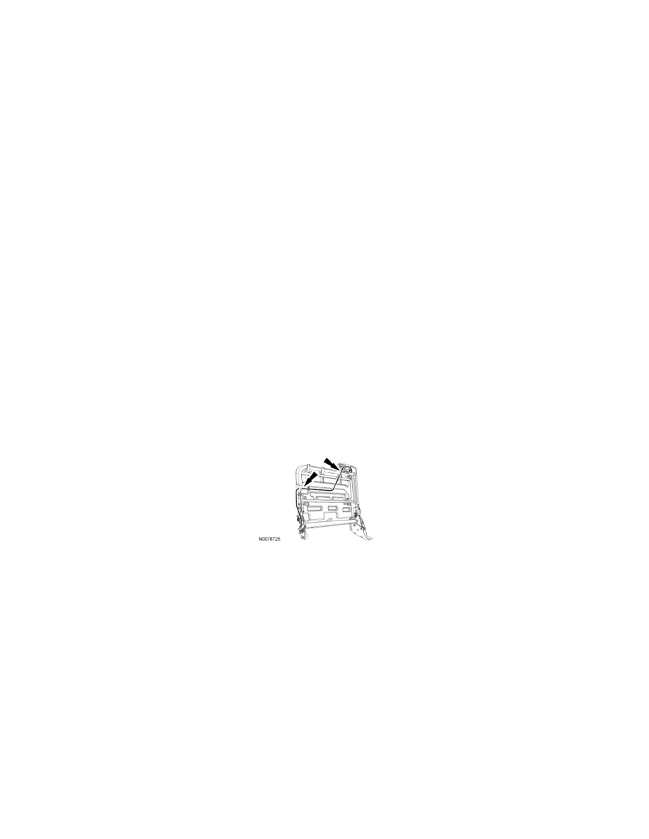
6. NOTE: The cable is to move freely after assembly.
Position the backrest to the inboard and outboard latches and route the cable between the backrest frame and support panel.
-
The cable is to pass between the backrest frame and the backrest support at the 2 points shown.