
Explorer 4WD V6-4.0L (2009)
Yes
CONNECT the negative battery cable. GO to S28.
No
If the vehicle is equipped with a 4X4 control module, GO to S21.
If the vehicle is not equipped with a 4X4 control module, GO to S22.
-------------------------------------------------
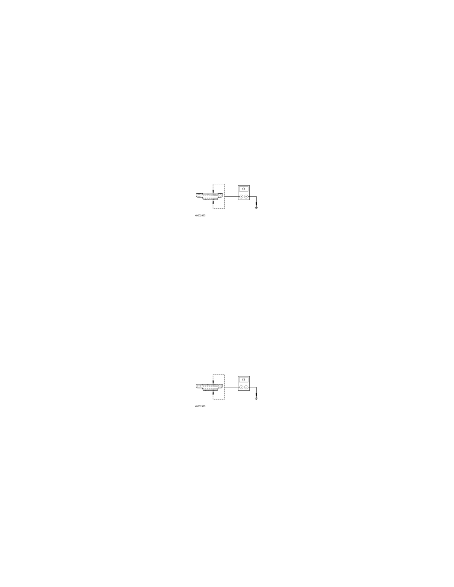
S21 CHECK THE HS-CAN (+) AND HS-CAN (-) CIRCUITS FOR A SHORT TO GROUND WITH THE 4X4 CONTROL MODULE
DISCONNECTED
-
Disconnect: 4X4 Control Module C281a.
-
Measure the resistance between the DLC C251-6, circuit VDB04 (WH/BU), harness side and ground; and between the DLC C251-14, circuit
VDB05 (WH), harness side and ground.
-
Are the resistances greater than 1,000 ohms?
Yes
CONNECT the negative battery cable. GO to S29.
No
GO to S22.
-------------------------------------------------
S22 CHECK THE HS-CAN (+) AND HS-CAN (-) CIRCUITS FOR A SHORT TO GROUND WITH THE OCSM DISCONNECTED
-
Disconnect: OCSM C3159.
-
Measure the resistance between the DLC C251-6, circuit VDB04 (WH/BU), harness side and ground; and between the DLC C251-14, circuit
VDB05 (WH), harness side and ground.
-
Are the resistances greater than 1,000 ohms?
Yes
CONNECT the negative battery cable. GO to S30.
No
If the vehicle is equipped with an APIM, GO to S23.
If the vehicle is not equipped with an APIM, GO to S24.
-------------------------------------------------
S23 CHECK THE HS-CAN (+) AND HS-CAN (-) CIRCUITS FOR A SHORT TO GROUND WITH THE APIM DISCONNECTED
-
Disconnect: APIM C3342.
-
Measure the resistance between the DLC C251-6, circuit VDB04 (WH/BU), harness side and ground; and between the DLC C251-14, circuit
VDB05 (WH), harness side and ground.