
Explorer 4WD V6-4.0L (2009)
Removal and Installation
NOTICE: Suspension fasteners are critical parts because they affect performance of vital components and systems and their failure may result
in major service expense. New parts must be installed with the same part numbers or equivalent part, if replacement is necessary. Do not use a
replacement part of lesser quality or substitute design. Torque values must be used as specified during reassembly to make sure of correct
retention of these parts.
1. Remove the wheel and tire.
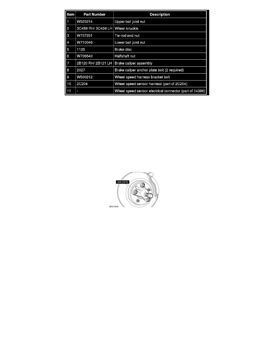
2. Remove and discard the halfshaft nut.
-
To install, tighten to 250 Nm (184 lb-ft).
3. Using the Front Wheel Hub Remover, separate the outboard CV joint from the wheel hub.
4. NOTICE: Do not allow the caliper and anchor plate assembly to hang from the brake hose or damage to the hose can occur.
Remove the bolts and position the caliper, pads and anchor plate assembly aside.
-
Discard the bolts.
-
Support the caliper and anchor plate assembly using mechanic's wire.
-
To install, tighten to 165 Nm (122 lb-ft).
5. Remove the brake disc.
6. Remove the wheel speed sensor harness bracket bolt from the wheel knuckle.
-
To install, tighten to 8 Nm (71 lb-in).
7. Disconnect the wheel speed sensor harness pin-type retainers.
8. Disconnect the wheel speed sensor electrical connector.
9. Remove and discard the tie-rod end nut.
-
To install, tighten the new nut to 103 Nm (76 lb-ft).
10. NOTICE: Do not use a hammer to separate the tie rod from the wheel knuckle or damage to the wheel knuckle can result.
NOTICE: Do not damage the tie-rod boot while installing the C-Frame and Screw.