
Explorer 4WD V6-4.0L VIN E (1999)
Multiplex Communication Network: Pinout Values and Diagnostic Parameters
Inspection and Verification (Start Here)
1. Verify the customer concern.
2. Visually inspect for obvious signs of electrical damage.
VISUAL INSPECTION CHART
Electrical
^
Central Junction Box (CJB) Fuse 5 (10 A)
^
Damaged wiring harness
^
Loose or corroded connectors
^
4-wheel anti-lock brake control module
^
Restraint Control Module (RCM)
^
Generic Electronic Module (GEM)/Central Timer Module (CTM)
^
Powertrain Control Module (PCM)
^
Parking Aid Module (PAM) (optional)
^
Remote Anti-theft Personality (RAP) module (optional)
^
Air suspension control module (optional)
^
Passive Anti-Theft System (PATS) module
^
Driver Seat Module (DSM) (optional)
^
Electronic Automatic Temperature Control (EATC) module (optional)
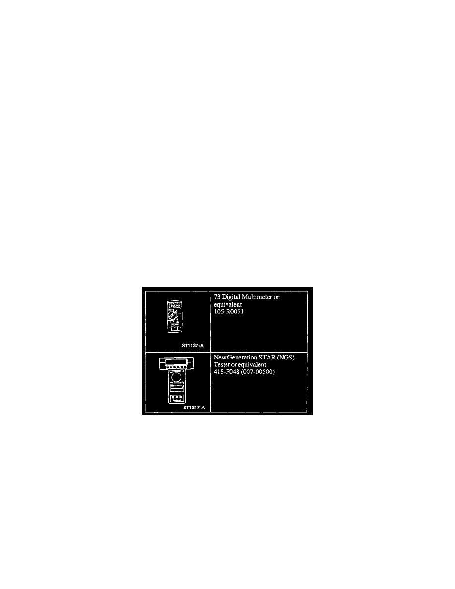
3. If the concern remains after the inspection, connect the New Generation STAR (NGS) Tester to the Data Link Connector (DLC) located beneath
the instrument panel and select the vehicle to be tested from the NGS menu. If the NGS does not communicate with the vehicle:
^
check that the program card is properly installed.
^
check the connections to the vehicle.
^
check the ignition switch position is in RUN. If the NGS still does not communicate with the vehicle, go to Pinpoint Test M. See: Module
Communication Network/Pinpoint Tests/M: No Module/Network Communication - No Power to the NGS Tester
4. Go to Pinpoint Test PC. See: Module Communication Network/System Precheck