
Explorer AWD V6-4.0L VIN K Flex Fuel (2003)
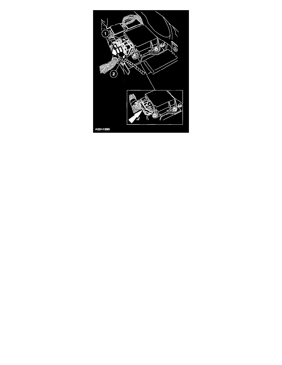
1. Disconnect the large restraints control module (RCM) electrical connector.
1
Pinch the thumb tab and pivot the connector position assurance lever all the way back until it stops.
2
Pull out and disconnect the RCM electrical connector.
INSTALLATION
1. NOTE: Make sure the battery negative cable is still disconnected before continuing with the installation portion of this procedure.
To install, reverse the removal procedure.
2. Connect the battery ground cable.
3. With the restraint system diagnostic tools installed at all deployable devices, prove out the supplemental restraint system (SRS). See: Air Bag(s)
Arming and Disarming/Service and Repair/Prove Out Procedure
4. Disconnect the battery ground cable and wait at least one minute.
5. WARNING: To reduce the risk of serious personal injury, read and follow all warnings, cautions, notes, and instructions in the
supplemental restraint system (SRS) deactivation/reactivation procedure.
Reactivate the supplemental restraint system (SRS).
6. Connect the battery ground cable.
7. WARNING: The restraint system diagnostic tool is for restraint system service only. Remove from the vehicle prior to road use. Failure
to remove could result in injury and possible violation of vehicle safety standards.
With all the restraint system diagnostic tools removed, prove out the supplemental restraint system (SRS). See: Air Bag(s) Arming and
Disarming/Service and Repair/Prove Out Procedure
Item 1: Large Electrical Connector Installation Note