
Explorer AWD V6-4.0L VIN K Flex Fuel (2003)
Part 2
6. NOTE: If the clockspring is to be reinstalled, do not allow the clockspring to turn from its removal position.
Remove the components in the order indicated in the illustration and table.
7. Connect the battery ground cable.
8. With the restraint system diagnostic tools installed at all deployable devices, prove out the supplemental restraint system (SRS). See: Air Bag(s)
Arming and Disarming/Service and Repair/Prove Out Procedure
9. Disconnect the battery ground cable and wait at least one minute.
Item 3: Gear Shift Lever Boot Removal Note
1. CAUTION: Do not use a prying device to detach the shift lever boot or damage to the steering column shrouds can result.
Detach the gear selector boot from the shrouds.
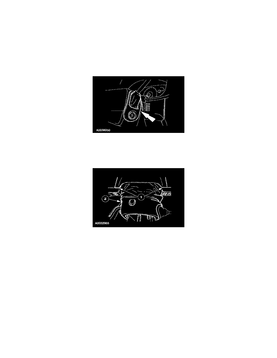
Item 6: Upper Steering Column Shroud Removal Note
1. Remove e upper steering column shroud.
1
Lift where shown to release the retaining clips, and rotate the upper steering column trim panel out of the instrument cluster finish panel.
2
Remove the upper steering column shroud hard shell.
Item 7: Tape Removal Note
1. If installing the same clockspring, apply two strips of masking tape across the clockspring to prevent accidental rotation when the clockspring is
removed.
Item 9: Multi-function Switch Removal Note
1. While releasing the retaining tab at the top of the multi-function switch, slide the multi-function switch up and out of the way.
Item 12: Clockspring Connectors Removal Note