Explorer AWD V8-4.6L (2010)

Trailer Lamps: Initial Inspection and Diagnostic Overview
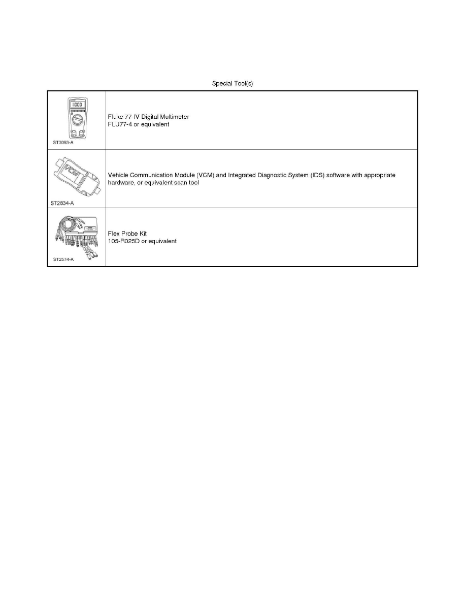
Special Tool(s) Used With Diagnostics
Trailer Lamps
Principles Of Operation
Trailer Lamps
Principles of Operation
NOTE: The Smart Junction Box (SJB) is also known as the Generic Electronic Module (GEM).
The SJB uses existing inputs to determine if voltage needs to be supplied to the individual trailer stop/turn lamps. The SJB has separate drivers that
provide voltage for the trailer stop/turn lamps. The trailer parking and reversing lamps share the vehicle lighting outputs.
The vehicle is supplied with wiring to support an aftermarket Trailer Brake Control (TBC) module (installed by the customer).
The trailer tow battery charging is controlled by a relay. When the ignition switch is in the RUN or ACC position, the trailer tow battery charge relay is
energized, which routes voltage to the trailer tow connector.
Field-Effect Transistor (FET) Protection
Field-Effect Transistor (FET) is a type of transistor that when used with module software can be used to monitor and control current flow on module
outputs. The FET protection strategy is used to prevent module damage in the event of excessive current flow.
The SJB utilizes a FET protective circuit strategy for many of its outputs (for example, a headlamp output circuit). Output loads (current level) are
monitored for excessive current (typically short circuits) and are shut down (turns off the voltage or ground provided by the module) when a fault event
is detected. A continuous DTC is stored at the fault event and a cumulative counter is started.
When the demand for the output is no longer present, the module resets the FET circuit protection to allow the circuit to function. The next time the
driver requests a circuit to activate that has been shut down by a previous short (FET protection) and the circuit remains shorted, the FET protection
shuts off the circuit again and the cumulative counter advances.
When the excessive circuit load occurs often enough, the module shuts down the output until a repair procedure is carried out. Each FET protected
circuit has 3 predefined levels of short circuit tolerance based on the harmful effect of each circuit fault on the FET and the ability of the FET to
withstand it. A module lifetime level of fault events is established based upon the durability of the FET. If the total tolerance level is determined to be
600 fault events, the 3 predefined levels would be 200, 400 and 600 fault events.
When each tolerance level is reached, the continuous DTC that was stored on the first failure cannot be cleared by a command to clear the continuous
