
Explorer AWD V8-4.6L (2010)
Timing Chain: Diagrams
Timing Chain Alignment
NOTICE: Damage to the camshaft phaser sprocket assembly will occur if mishandled or used as a lifting or leveraging device.
NOTICE: Only use hand tools to remove the camshaft phaser sprocket assembly or damage may occur to the camshaft or camshaft phaser
unit.
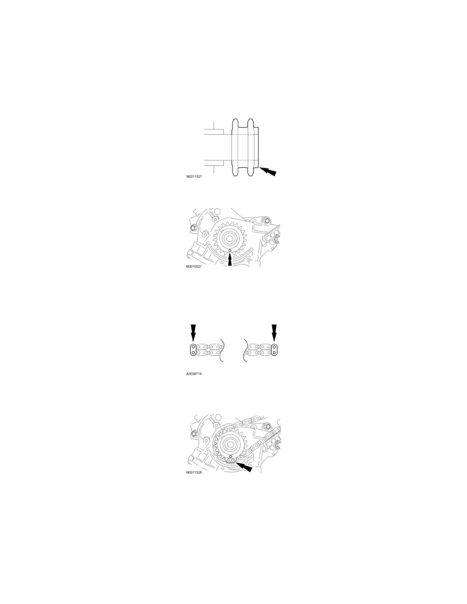
Install the crankshaft sprocket, making sure the flange faces forward.
Rotate the crankshaft to position the crankshaft sprocket timing mark in the 6 o'clock position.
NOTICE: Timing chain procedures must be followed exactly or damage to valves and pistons will result.
If the colored links are not visible, mark one link on one end and one link on the other end and use as timing marks.
Position the lower end of the LH (inner) timing chain on the crankshaft sprocket, aligning the timing mark on the outer flange of the crankshaft sprocket
with the single colored (marked) link on the chain.
NOTE: Make sure the upper half of the timing chain is below the tensioner arm dowel.
Position the LH timing chain on the camshaft sprocket. Make sure the camshaft sprocket timing mark is aligned with the colored (marked) chain link.