
Explorer AWD V8-4.6L (2010)
REPAIR the circuit. CONNECT the negative battery cable. CLEAR the DTCs. REPEAT the network test with the scan tool.
-------------------------------------------------
G6 CHECK THE IC VOLTAGE SUPPLY CIRCUITS FOR AN OPEN
-
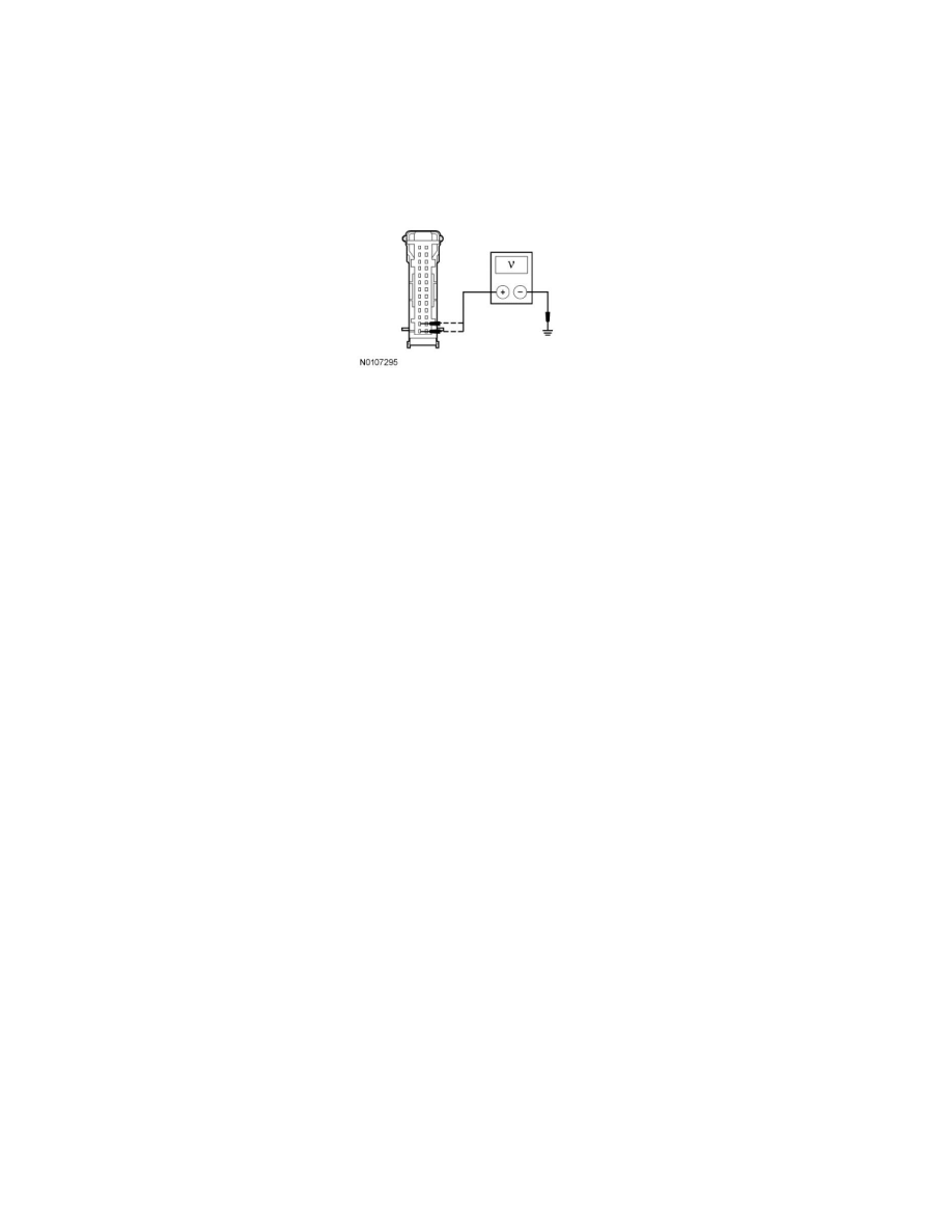
Ignition ON.
-
Measure the voltage between the IC C220-1, circuit SBP24 (VT/RD), harness side and ground; and between the IC C220-2, circuit CDC34
(WH/OG), harness side and ground.
-
Are the voltages greater than 10 volts?
Yes
GO to G7.
No
VERIFY SJB fuse 26 (10A) or fuse 29 (5A) is OK. If OK, REPAIR the circuit in question. If not OK, REFER to the Wiring Diagrams to IDENTIFY the
possible causes of the circuit short. CLEAR the DTCs. REPEAT the network test with the scan tool. See: Diagrams/Electrical Diagrams/Diagrams By
Number
-------------------------------------------------
G7 CHECK FOR CORRECT IC OPERATION
-
Disconnect the IC connector.
-
Check for:
-
corrosion
-
damaged pins
-
pushed-out pins
-
Connect the IC connector and make sure it seats correctly.
-
Operate the system and verify the concern is still present.
-
Is the concern still present?
Yes
INSTALL a new IC. REFER to Instrument Panel, Gauges and Warning Indicators. CLEAR the DTCs. REPEAT the network test with the scan tool.
No
The system is operating correctly at this time. The concern may have been caused by a loose or corroded connector. CLEAR the DTCs. REPEAT the
network test with the scan tool.
-------------------------------------------------
Pinpoint Test H: The Smart Junction Box (SJB) Does Not Respond To The Scan Tool
Communications Network
Pinpoint Tests
Pinpoint Test H: The Smart Junction Box (SJB) Does Not Respond To The Scan Tool
Refer to Wiring Diagram Set 10, Grounds for schematic and connector information. See: Diagrams/Electrical Diagrams/Diagrams By Number
Refer to Wiring Diagram Set 13, Power Distribution/SJB for schematic and connector information. See: Diagrams/Electrical Diagrams/Diagrams By