
Explorer AWD V8-4.6L (2010)
Communications Network
Pinpoint Tests
Pinpoint Test S: No Medium Speed Controller Area Network (MS-CAN) Communication, All Modules Are Not Responding
Refer to Wiring Diagram Set 14, Module Communications Network for schematic and connector information. See: Diagrams/Electrical
Diagrams/Diagrams By Number
Normal Operation
The Medium Speed Controller Area Network (MS-CAN) uses an unshielded twisted pair cable which provide the network connection to all modules on
the network.
This pinpoint test is intended to diagnose the following:
-
Wiring, terminals or connectors
-
Data Link Connector (DLC)
-
Accessory Protocol Interface Module (APIM) (if equipped)
-
Audio Control Module (ACM)
-
Driver Seat Module (DSM) (if equipped)
-
Global Positioning System Module (GPSM) (if equipped)
-
HVAC module (if equipped)
-
Instrument Cluster (IC)
-
Parking Aid Module (PAM) (if equipped)
-
Power Running Board (PRB) module (if equipped)
-
Rear Entertainment Module (RETM) (if equipped)
-
Satellite Digital Audio Receiver System (SDARS) module (if equipped)
-
Smart Junction Box (SJB)
PINPOINT TEST S: NO MS-CAN COMMUNICATION, ALL MODULES ARE NOT RESPONDING
NOTICE: Use the correct probe adapter(s) when making measurements. Failure to use the correct probe adapter(s) may damage the
connector.
NOTE: Most faults are due to connector and/or wiring concerns. Carry out a thorough inspection and verification before proceeding with the pinpoint
test. See: Initial Inspection and Diagnostic Overview/Module Communications Network/Inspection and Verification
NOTE: Failure to disconnect the battery when instructed will result in false resistance readings. Refer to Battery.
-------------------------------------------------
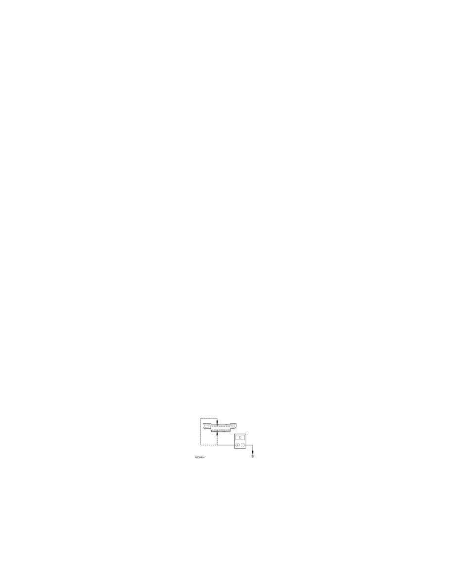
S31 CHECK THE MS-CAN (+) AND MS-CAN (-) CIRCUITS FOR A SHORT TO GROUND WITH THE ACM DISCONNECTED
-
Disconnect: ACM C290b.
-
Measure the resistance between the DLC C251-3, circuit VDB06 (GY/OG), harness side and ground; and between the DLC C251-11, circuit
VDB07 (VT/OG), harness side and ground.
-
Are the resistances greater than 1,000 ohms?
Yes
CONNECT the negative battery cable. GO to S50.
No
GO to S32.
-------------------------------------------------
S32 VERIFY VEHICLE EQUIPMENT - HVAC MODULE