
Explorer AWD V8-4.6L (2010)
-
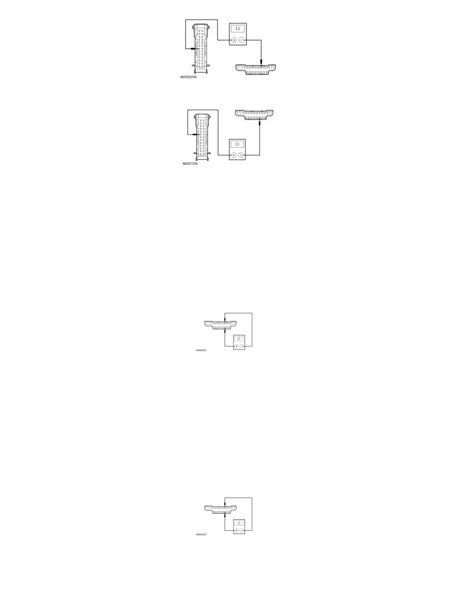
Measure the resistance between the IC C220-8, circuit VDB05 (WH), harness side and the DLC C251-14, circuit VDB05 (WH), harness side.
-
Are the resistances less than 5 ohms?
Yes
CONNECT the negative battery cable. GO to U34.
No
REPAIR the circuit in question. CONNECT the negative battery cable. CLEAR the DTCs. REPEAT the network test with the scan tool.
-------------------------------------------------
U9 CHECK THE HS-CAN (+) AND HS-CAN (-) CIRCUITS FOR A SHORT TOGETHER
-
Measure the resistance between the DLC C251-6, circuit VDB04 (WH/BU), harness side and the DLC C251-14, circuit VDB05 (WH), harness
side.
-
Is the resistance less than 5 ohms?
Yes
GO to U11.
No
GO to U10.
-------------------------------------------------
U10 CHECK THE HS-CAN CIRCUITS FOR AN OPEN AT THE DLC
-
Measure the resistance between the DLC C251-6, circuit VDB04 (WH/BU), harness side and the DLC C251-14, circuit VDB05 (WH), harness
side.
-
Is the resistance greater than 10,000 ohms?
Yes