
Explorer AWD V8-4.6L (2010)
Yes
CONNECT the negative battery cable. GO to U29.
No
GO to U22.
-------------------------------------------------
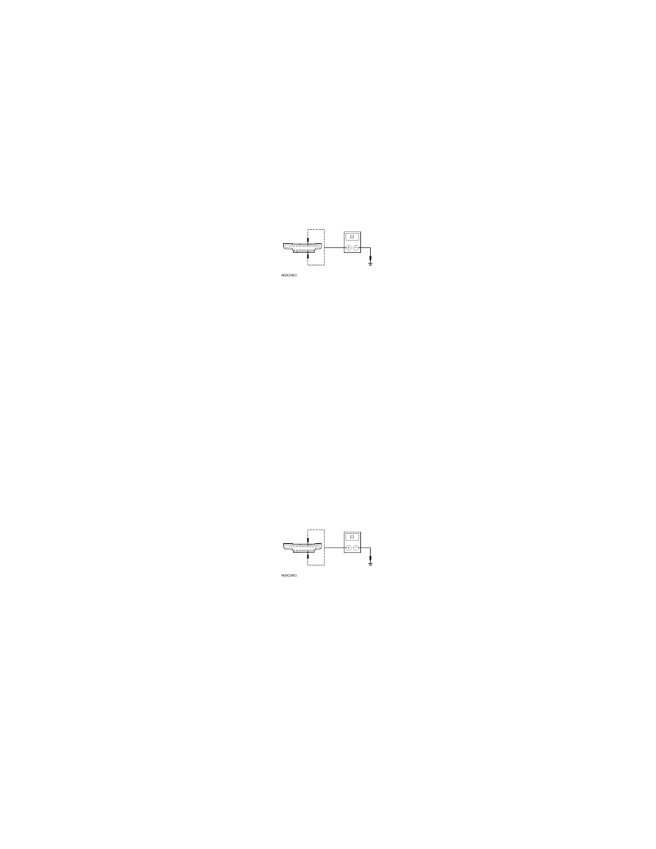
U22 CHECK THE HS-CAN (+) AND HS-CAN (-) CIRCUITS FOR A SHORT TO GROUND WITH THE OCSM DISCONNECTED
-
Disconnect: OCSM C3159.
-
Measure the resistance between the DLC C251-6, circuit VDB04 (WH/BU), harness side and ground; and between the DLC C251-14, circuit
VDB05 (WH), harness side and ground.
-
Are the resistances greater than 1,000 ohms?
Yes
CONNECT the negative battery cable. GO to U30.
No
If the vehicle is equipped with an APIM, GO to U23.
If the vehicle is not equipped with an APIM, GO to U24.
-------------------------------------------------
U23 CHECK THE HS-CAN (+) AND HS-CAN (-) CIRCUITS FOR A SHORT TO GROUND WITH THE APIM DISCONNECTED
-
Disconnect: APIM C3342.
-
Measure the resistance between the DLC C251-6, circuit VDB04 (WH/BU), harness side and ground; and between the DLC C251-14, circuit
VDB05 (WH), harness side and ground.
-
Are the resistances greater than 1,000 ohms?
Yes
CONNECT the negative battery cable. GO to U31.
No
GO to U24.
-------------------------------------------------
U24 CHECK THE HS-CAN (+) AND HS-CAN (-) CIRCUITS FOR A SHORT TO GROUND WITH THE RCM DISCONNECTED
-
Disconnect: RCM C310b.
-
Measure the resistance between the DLC C251-6, circuit VDB04 (WH/BU), harness side and ground; and between the DLC C251-14, circuit
VDB05 (WH), harness side and ground.