
Explorer AWD V8-4.6L (2010)
System (SRS) Depowering and Repowering in the General Procedures.
3. Remove the front floor console. For additional information, refer to Instrument Cluster / Carrier &/or Interior Moulding / Trim.
4. Disconnect the large RCM electrical connector.
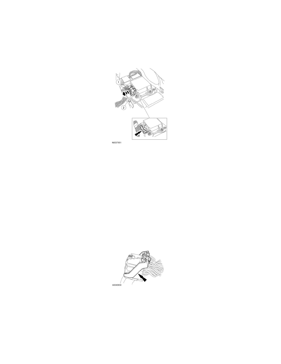
1. Pinch the thumb tab and pivot the large RCM electrical connector position assurance lever all the way back until it stops.
2. Pull out and disconnect the large RCM electrical connector.
5. Press to release the locking tab and disconnect the small RCM electrical connector.
6. Remove the 3 RCM nuts.
7. Remove the RCM.
Installation
1. Install the RCM.
2. Install the 3 RCM nuts.
-
Tighten to 12 Nm (106 lb-in).
3. Connect the small RCM electrical connector.
4. NOTE: The RCM has been removed for clarity.
On the large RCM electrical connector, place the connector position assurance lever in the full release position.
5. NOTICE: Putting the large electrical connector into the Restraints Control Module (RCM) on an angle may cause bad electrical
connections and damage components.
Position the large electrical connector into the RCM.