
Explorer Sport 4WD V6-245 4.0L SOHC VIN K SFI (2001)
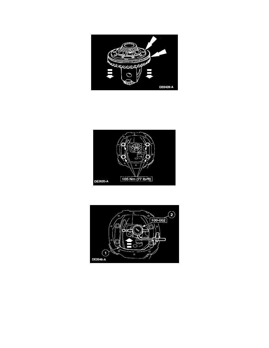
8. CAUTION:
^
Do not damage the differential ring gear bolt hole threads.
^
If removing the anti-lock speed sensor ring, discard it, and install a new anti-lock speed sensor ring during installation.
Insert a punch in the bolt holes, and drive off the differential ring gear and, if necessary, the anti-lock speed sensor ring.
9. If the differential ring gear backface runout measurement, taken at the beginning of this procedure, did not exceed the specification, proceed to the
appropriate procedure as necessary: Drive Pinion, Differential Case and Ring Gear-Conventional or Differential Case and Ring
Gear-Traction-Lok, or to Installation in this procedure. If the differential ring gear backface runout measurement, taken at the beginning of this
procedure, exceeded the specification, the cause may be a warped differential ring gear, differential case/differential bearing damage. Proceed as
follows to verify the cause of the excessive runout.
10. Position the differential assembly, including the differential bearing cups and differential bearing shims, in the differential housing. Install the
bearing caps and the bolts.
11. Position the special tool.
1. Rotate the differential case to verify that the differential bearings have seated correctly.
2. Position the special tool.