
Explorer Sport Trac 2WD V6-4.0L (2009)
positions can be recalled by either pressing the memory switches or by unlocking the vehicle with the remote transmitters.
The DSM also receives inputs from the driver seat switch and outputs the requested command to the seats. If the vehicle has memory, the DSM will also
receive inputs from the adjustable pedal switch and outputs the requested commands to the adjustable pedal motor. The memory driver seat feature
allows the driver to program a personalized seat position that can be recalled using the memory switches or the Remote Keyless Entry (RKE) transmitter.
Refer to Locks for the remote memory activation general procedure.
The DSM is on the Medium Speed Controller Area Network (MS-CAN). The DSM supports inter-module and scan tool communications.
Special Tools Used With Diagnostics
Driver Seat Module (DSM)
Inspection And Verification
Smart Junction Box (SJB)
Inspection and Verification
1. Verify the customer concern.
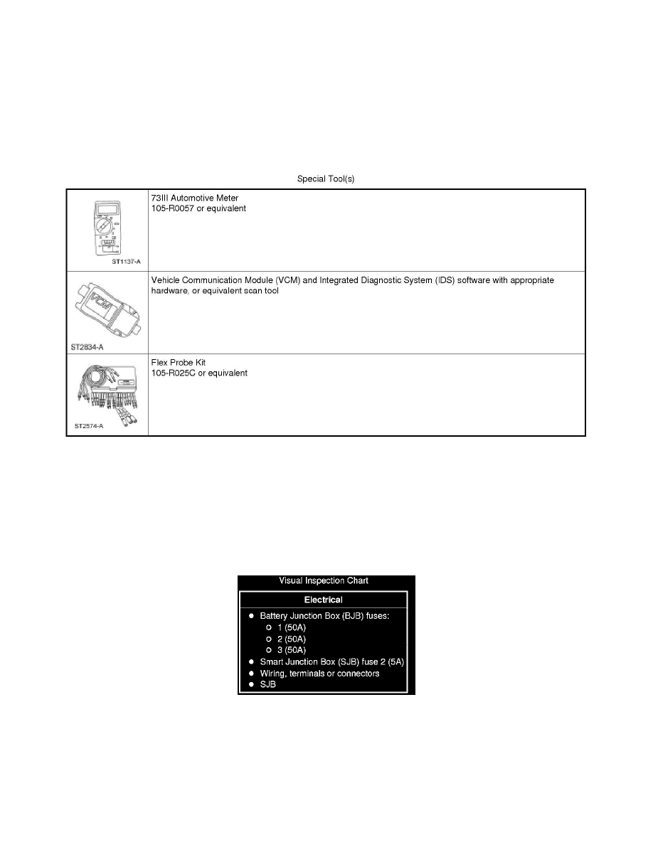
2. Visually inspect for obvious signs of electrical damage.
Visual Inspection Chart
3. If an obvious cause for an observed or reported concern is found, correct the cause (if possible) before proceeding to the next step.
4. NOTE: Make sure to use the latest scan tool software release.
If the cause is not visually evident, connect the scan tool to the Data Link Connector (DLC).
5. NOTE: The Vehicle Communication Module (VCM) LED prove-out confirms power and ground from the DLC are provided to the VCM.