
Explorer Sport Trac 2WD V6-4.0L (2009)
Yes
GO to A3.
No
REFER to Computers and Control Systems Information, Pinpoint Tests, pinpoint test QA to diagnose no communication with the PCM.
-------------------------------------------------
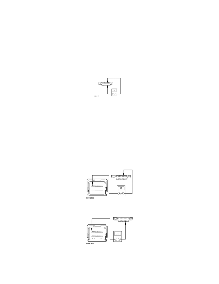
A3 CHECK THE HS-CAN TERMINATION RESISTANCE
-
Ignition OFF.
-
Disconnect: Negative Battery Cable.
-
Measure the resistance between the Data Link Connector (DLC) C251-6, circuit VDB04 (WH/BU), harness side and the DLC C251-14, circuit
VDB05 (WH), harness side.
-
Is the resistance between 54 and 66 ohms?
Yes
CONNECT the negative battery cable. GO to A5.
No
GO to A4.
-------------------------------------------------
A4 CHECK THE CAN CIRCUITS BETWEEN THE DLC AND THE PCM FOR AN OPEN
-
Disconnect: PCM C175b.
-
Measure the resistance between the PCM C175b-11, circuit VDB04 (WH/BU), harness side and the DLC C251-6, circuit VDB04 (WH/BU),
harness side.
-
Measure the resistance between the PCM C175b-23, circuit VDB05 (WH), harness side and the DLC C251-14, circuit VDB05 (WH), harness
side.
-
Are the resistances less than 5 ohms?
Yes
CONNECT the negative battery cable. GO to A5.