
Explorer Sport Trac 2WD V6-4.0L (2009)
6. Remove and discard the shock absorber lower bolt and flag nut.
7. Remove and discard the upper ball joint nut.
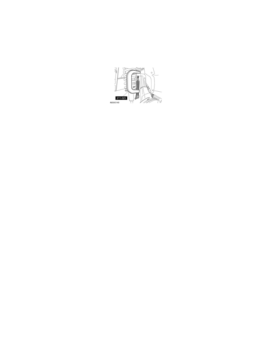
8. NOTICE: Do not use a hammer to separate the ball joint from the wheel knuckle or damage to the wheel knuckle can result.
NOTICE: Do not damage the ball joint boot while installing the C-Frame and Screw.
Using the C-Frame and Screw, separate the upper ball joint from the wheel knuckle.
9. While lowering the suspension, remove the shock and spring assembly.
Installation
NOTICE: Before tightening any suspension bushing fasteners, use a suitable jack to raise the suspension until the distance between the center
of the hub and the lip of the fender is equal to the measurement taken in Step 1 (curb height). This will prevent unequal clamp load and bushing
damage.
NOTE: For additional information on the disassembly and assembly of the shock absorber and spring assembly, refer to Shock Absorber and Spring
Assembly.
1. Install the shock absorber and spring assembly.
2. Connect the upper ball joint to the wheel knuckle and install the new upper ball joint nut.
-
Tighten to 55 Nm (41 lb-ft).
3. NOTE: Do not tighten the bolt at this time.
Install the new shock absorber lower bolt and flag nut.
4. Using a suitable jack, raise the suspension until the distance between the center of the hub and the lip of the fender is equal to the measurement
taken in Step 1 (curb height).
5. Position the stabilizer bar link and install the new nut.
-
Tighten to 35 Nm (26 lb-ft).
6. Tighten the shock absorber lower bolt to 250 Nm (258 lb-ft).
7. Install the 3 new shock absorber upper mount nuts.
-
Tighten to 30 Nm (22 lb-ft).
8. Remove the jack.
9. Install the wheel and tire.
10. Check and if necessary, align the front end.