
Explorer Sport Trac 2WD V8-4.6L (2008)
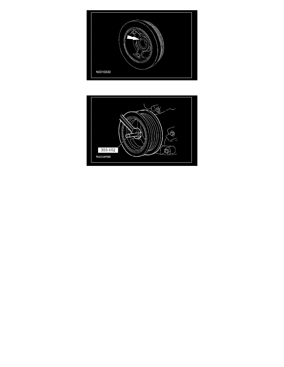
9. Using the special tool, install the crankshaft pulley.
10. Using a new crankshaft pulley bolt, install the bolt and washer and tighten the bolt in 4 stages.
^
Stage 1: Tighten to 90 Nm (66 lb-ft).
^
Stage 2: Loosen 360 degrees.
^
Stage 3: Tighten to 50 Nm (37 lb-ft).
^
Stage 4: Tighten an additional 90 degrees.
11. Connect the CKP sensor electrical connector.
12. Attach the transmission cooler tube bracket to the engine front cover and install the nut.
^
Tighten to 12 Nm (9 lb-ft).
13. Attach the battery cable bracket to the front cover and install the nut.
^
Tighten to 10 Nm (89 lb-in).
14. Attach the PSP hose bracket to the battery cable bracket and install the nut.
^
Tighten to 10 Nm (89 lb-in).
15. Position the power steering pump and install the stud bolts.
^
Tighten to 25 Nm (18 lb-ft).
16. Attach the wiring harness retainer to the power steering pump stud bolt.
17. Position the battery cable bracket on the power steering pump stud bolts and install the nuts.
^
Tighten to 10 Nm (89 lb-in).
18. Position the coolant pump pulley and install the bolts.
^
Tighten the bolts to 25 Nm (18 lb-ft).
19. Connect the LH CMP sensor electrical connector.
20. Position the LH radio interference capacitor and install the nut.
^
Tighten to 25 Nm (18 lb-ft).
21. Position the cooling fan wiring harness bracket and install the nut.
22. Connect the RH CMP sensor electrical connector.
23. Position the RH radio interference capacitor and install the nut.
^
Tighten to 25 Nm (18 lb-ft).
24. Install the LH valve cover.
25. Install the RH valve cover.
26. Install the RH side idler pulley.
27. Install the cooling fan shroud.
28. Fill the engine with clean engine oil.