
Explorer Sport Trac 2WD V8-4.6L (2008)
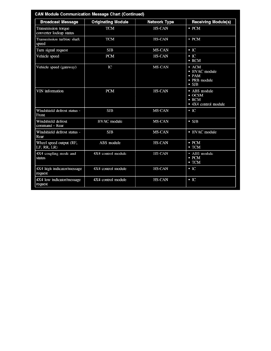
CAN Module Communication Message Chart (Part 5)
Inspection and Verification
INSPECTION AND VERIFICATION
This provides step-by-step module configuration procedures. Carry out the programmable module installation (PMI) procedure when another Vehicle
System directs to carry out configuration or when DTCs from the given list are present. See: Programming and Relearning
Principles of Operation
PRINCIPLES OF OPERATION
NOTE: The smart junction box (SJB) is also known as the generic electronic module (GEM).
Configurable modules accommodate a variety of vehicle options, eliminating the need for many unique modules for one vehicle line. These modules
must be configured when replaced as part of a repair procedure.
Configurable modules should not be exchanged between vehicles since the settings are unique to each vehicle. Failure to configure a new module may
result in improper operation and/or any of the following DTCs setting:
-
B2477 and/or B2141 - sets when a body/chassis module is not configured.
-
B2900 - sets when there is a VIN mismatch between the module with the B2900 and the PCM. Either the PCM or the body module stored VIN
may be incorrect.
-
P0602, P0605 and/or P1639 - sets when the PCM vehicle identification (VID) block is not configured or is configured incorrectly.
-
U0300 and/or U0301 - sets when the configuration between 2 or more modules do not match.
-
U2050 and/or U2051 - sets when a valid strategy/calibration is not present.
The following are the 3 different methods of configuration:
-
Programmable module installation (PMI)
-
Module reprogramming ("flashing")
-
Programmable parameters