
Explorer Sport Trac 2WD V8-4.6L (2008)
5. Remove the selector lever cable end from the manual control lever.
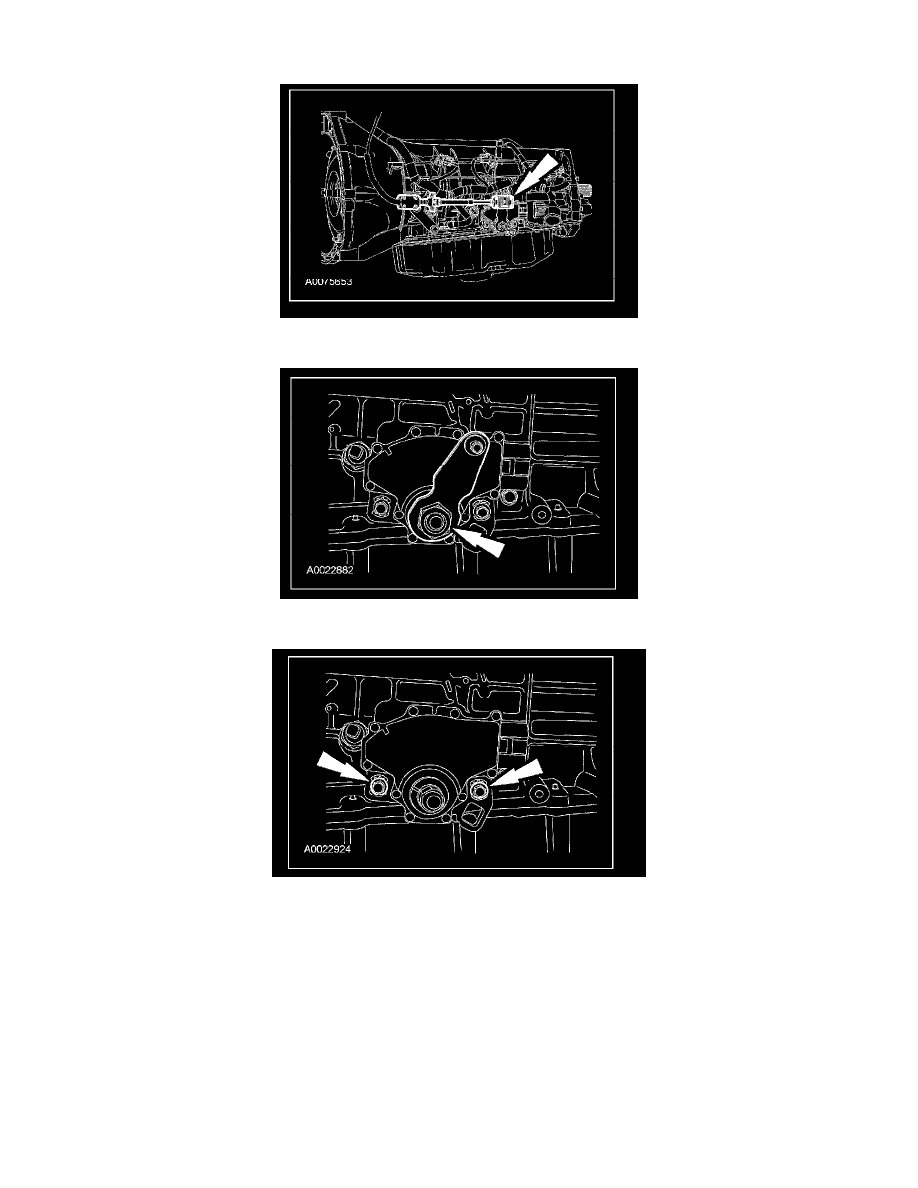
6. Remove the outer manual control lever nut and the manual control lever.
7. Loosen but do not remove the digital TR sensor screws.
8. Using the special tool, align the digital TR sensor and tighten the screws in an alternating sequence.
^
Tighten to 8 Nm (71 lb-inch).