
Explorer Sport Trac 4WD V6-245 4.0L SOHC VIN K SFI (2001)
Auxiliary Power Outlet: Diagram Information and Instructions
Early Production/Late Production Defined
NOTE: The build date can be found on the Vehicle Certification (VC) label.
Early Production
Built BEFORE 7/24/2000.
Uses the Remote Anti-Theft Personality (RAP) Module.
Late Production
Built AFTER 7/24/2000.
Uses the Central Security Module.
How to Find and Use These Diagrams
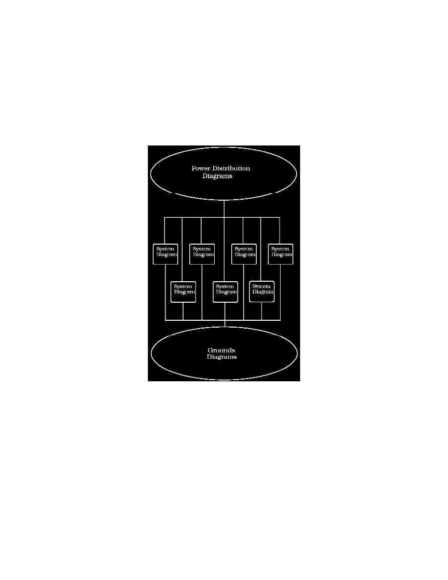
Diagrams are presented in three main categories:
^
Power Distribution Diagrams
^
System Diagrams
^
Grounds Diagrams
Note: All wiring connections between components are shown exactly as they exist in the vehicles. It is important to realize, however, that no attempt has
been made on the diagram to represent components and wiring as they physically appear on the vehicle. For example, a 4-foot length of wire is treated no
differently in a diagram from one which is only a few inches long. Furthermore, to aid in understanding electrical (electronic) operation, wiring inside
complicated components has been simplified.
Complete Circuit Operation
Each circuit is shown completely and independently in one set of diagrams. Other components which are connected to the circuit may not be shown
unless they influence the circuit operation.