
Explorer Sport Trac 4WD V6-245 4.0L SOHC VIN K SFI (2001)
Module Communication Network: Testing and Inspection
Module Communications Network
Initial Inspection
1. Verify the customer concern.
2. Visually inspect the following for obvious signs of electrical damage:
VISUAL INSPECTION CHART
Electrical
^
Central Junction Box (CJB) fuse 17 (20A)
^
Damaged wiring harness
^
Loose or corroded connectors
3. If the concern remains after the inspection, connect the diagnostic tool to the Data Link Connector (DLC) located beneath the instrument panel
and select the vehicle to be tested from the diagnostic tool menu. If the diagnostic tool does not communicate with the vehicle:
^
check that the program card is correctly installed.
^
check the connections to the vehicle.
^
check the ignition switch position.
If the diagnostic tool still does not communicate with the vehicle, go to Pinpoint Test I. See: Pinpoint Tests/Pinpoint Tests/Test I: No
Module/Network Communication
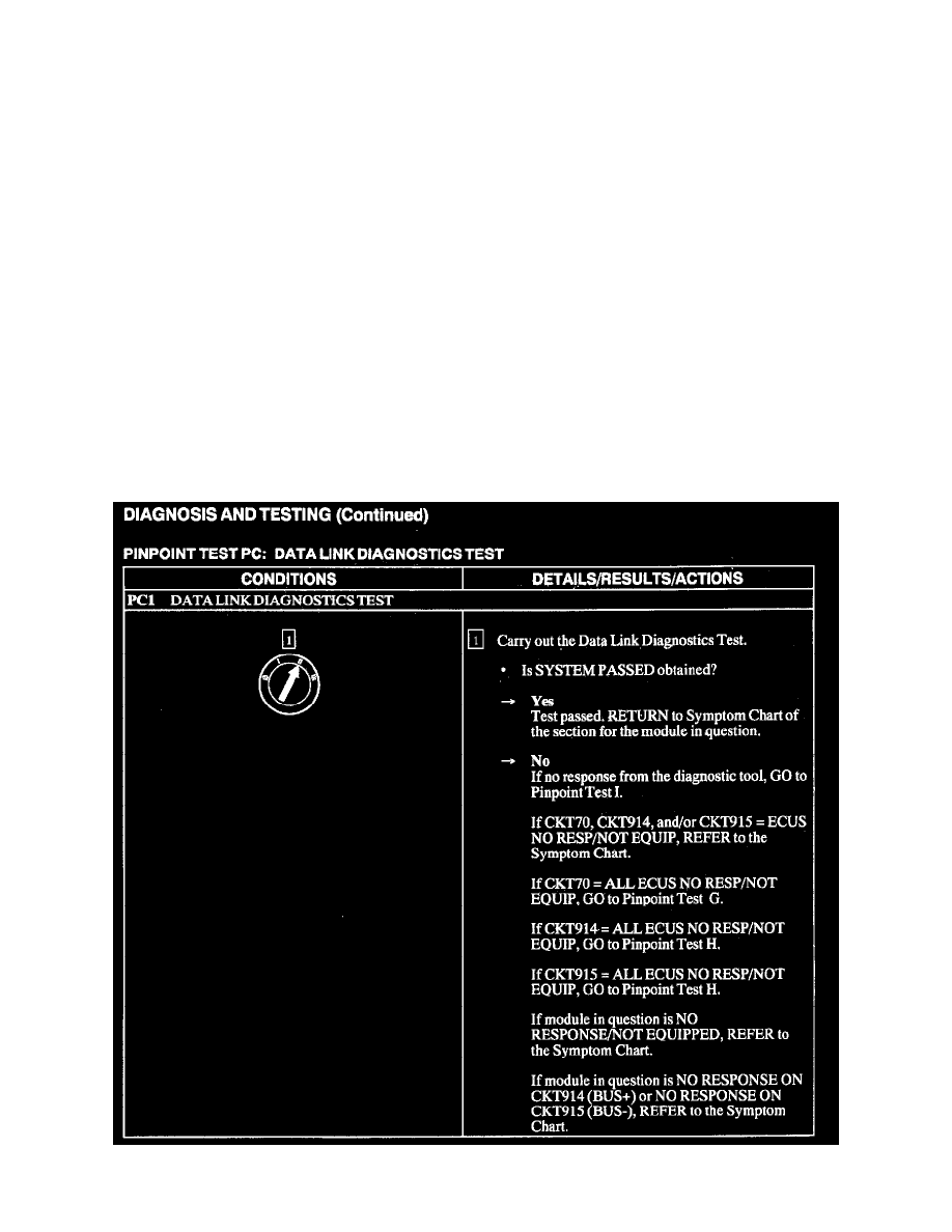
4. Go to Pinpoint Test PC. See: Pinpoint Tests/Pinpoint Test PC (Precheck)
PC1