
Explorer Sport Trac 4WD V6-4.0L VIN E (2007)
Part 2
Removal
NOTE:
-
The steps included in the SJB removal and installation procedure are critical to restoring the vehicle security and tire pressure monitoring systems
to normal operation. A new SJB is delivered in manufacturing mode with 6 pre-set diagnostic trouble codes (DTCs) related to the tire pressure
monitoring system. The presence of these DTCs requires the installation procedures be followed in order to clear the DTCs and enable normal SJB
operations.
-
Prior to the removal of the SJB, it is necessary to upload the module configuration information to the diagnostic tool. This information must be
downloaded to the new SJB after installation.
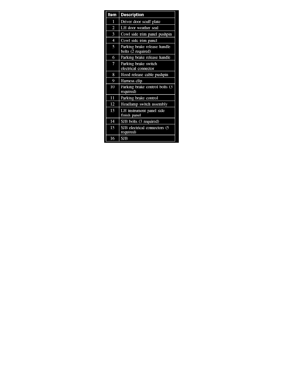
1. Remove the driver door scuff plate.
2. Position the LH door opening weather seal aside.
3. NOTE: While pulling the trim panel rearward, pull the hood release lever rearward in order for the release lever to slide through the trim panel.
Remove the pushpin and the cowl side trim panel.
4. Remove the 2 bolts and the parking brake release handle.
5. Disconnect the parking brake switch electrical connector.
6. Release the hood release cable pushpin from the parking brake control bracket.
7. Release the harness clip from the parking brake cable housing.
8. NOTE: Rotating the parking brake control counterclockwise allows enough access to clear the instrument panel reinforcement.
Remove the 3 bolts and position the parking brake control assembly under the brake pedal.
9. CAUTION: The lower side of the headlight switch bezel includes 2 tabs that slide down onto the instrument panel and may be broken if
any prying force is exerted in the lower area of the bezel.
Using a suitable tool, pry the mid-to-upper side of the headlight switch bezel away from the instrument panel, disconnect the 2 electrical
connectors and position the bezel assembly aside.
10. If necessary, push the LH instrument panel side finish panel out and position it aside.
11. Through the headlight switch bezel opening, remove the 2 SJB bolts.
12. From under the instrument panel, remove the third SJB bolt.
13. NOTE: The SJB electrical connector levers must click into a fully released position before they can be removed and must click into a fully closed