
Explorer Sport Trac 4WD V6-4.0L VIN E (2007)
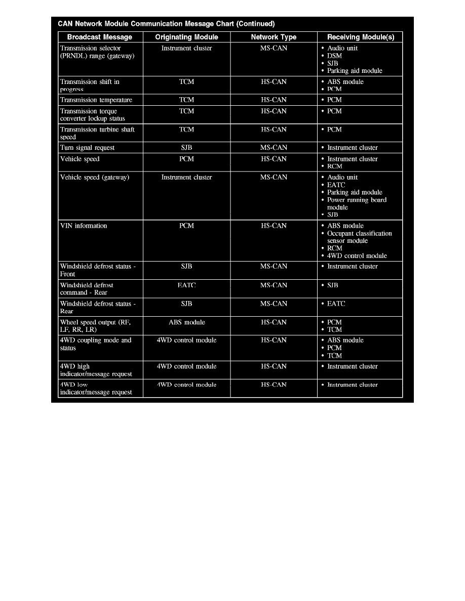
CAN Network Module Communication Message Chart (Part 5)
The chart describes the specific CAN network messages broadcast by each module, and the module(s) that receive the message:
Inspection and Verification
INSPECTION AND VERIFICATION
This provides step-by-step module configuration procedures. Carry out the programmable module installation (PMI) procedure when another directs to
carry out configuration or when DTCs from the list are present.
Principles of Operation
PRINCIPLES OF OPERATION
Configurable modules accommodate a variety of vehicle options, eliminating the need for many unique modules for one vehicle line. These modules
must be configured when replaced as part of a repair procedure.
Configurable modules should not be exchanged between vehicles since the settings are unique to each vehicle. Failure to configure a new module may
result in improper operation and/or any of the following DTCs setting:
-
B2477 and/or B2141 - sets when a body/chassis module is not configured.
-
B2900 - sets when there is a VIN mismatch between the module with the B2900 and the PCM. Either the PCM or the body module stored VIN