
Explorer Sport Trac 4WD V6-4.0L VIN E (2007)
E3-E4
Normal Operation
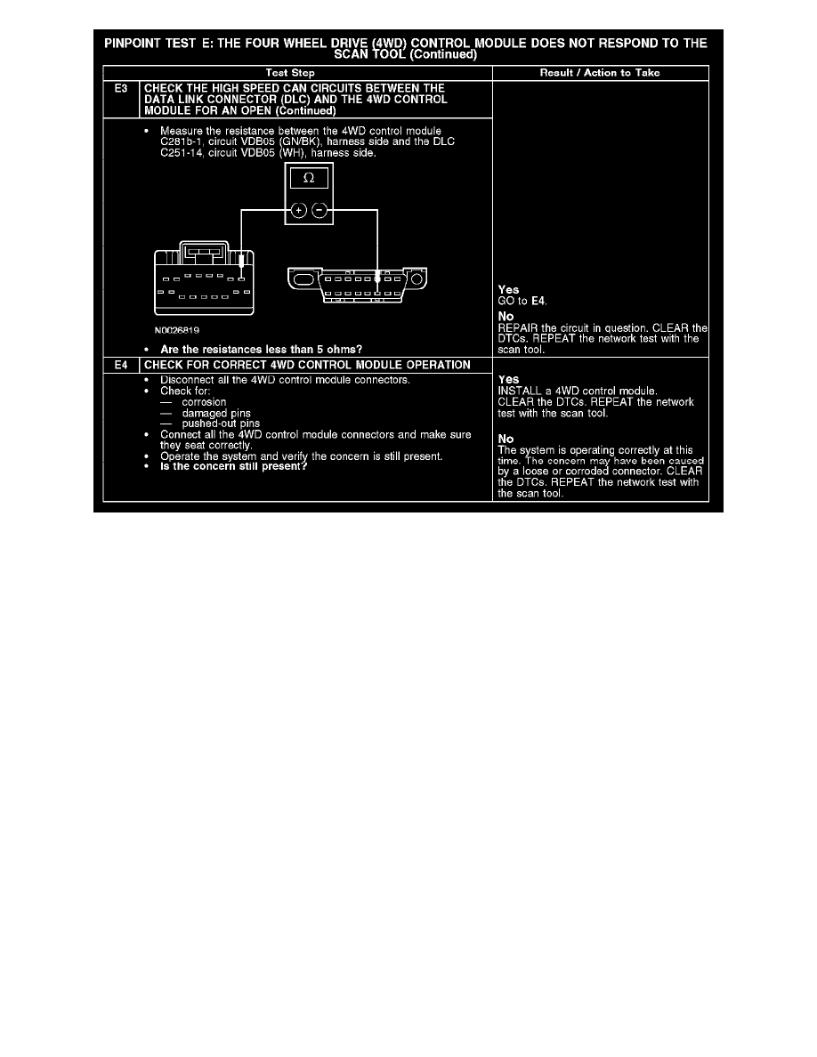
The 4WD control module communicates with the scan tool through the high speed controller area network (HS-CAN). Circuits VDB04 (WH/BU)
(HS-CAN +) and VDB05 (WH) (HS-CAN -) provide the network connection to the 4WD control module. The 4WD control module shares the
HS-CAN with powertrain control module (PCM), the transmission control module (TCM) (if equipped), the anti-lock brake system (ABS) module, the
restraints control module (RCM), the occupant classification sensor module and the instrument cluster. Voltage is supplied by circuits CBP18
(GY/OG), SBB23 (RD/WH) and SBB26 (RD/BK). Ground is supplied by circuits GD138 (BK/WH) and GD145 (BK/BU).
Possible Causes
-
Fuse
-
Circuit CBP18 (GY/OG) open
-
Circuit GD138 (BK/WH) open
-
Circuit GD145 (BK/BU) open
-
Circuit SBB23 (RD/WH) open
-
Circuit SBB26 (RD/BK) open
-
Circuit VDB04 (WH/BU) open (HS-CAN +)
-
Circuit VDB05 (WH) open (HS-CAN -)
-
4WD control module
Test F: The Occupant Classification Sensor Module Does Not Respond to the Scan Tool
PINPOINT TEST F: THE OCCUPANT CLASSIFICATION SENSOR MODULE DOES NOT RESPOND TO THE SCAN TOOL