
Explorer Sport Trac 4WD V6-4.0L VIN E (2007)
NOTE:
-
The air bag warning lamp illuminates when the RCM fuse is removed and the ignition switch is ON. This is normal operation and does not indicate
a supplemental restraint system (SRS) fault.
-
The SRS must be fully operational and free of faults before releasing the vehicle to the customer.
-
Repair is made by installing a new part only. If the new part does not correct the condition, install the original part and carry out the diagnostic
procedure again.
1. Depower the system.
2. Make sure the road wheels are in the straight-ahead position.
3. Tilt the steering wheel in the downward position and lock the tilt handle.
4. Remove the driver air bag module.
5. Remove the steering wheel.
6. Remove the 2 screws and the instrument panel (I/P) lower steering column opening cover.
7. Remove the 3 screws and the lower steering column shroud.
8. Remove the upper steering column shroud.
9. Disconnect the clockspring electrical connector.
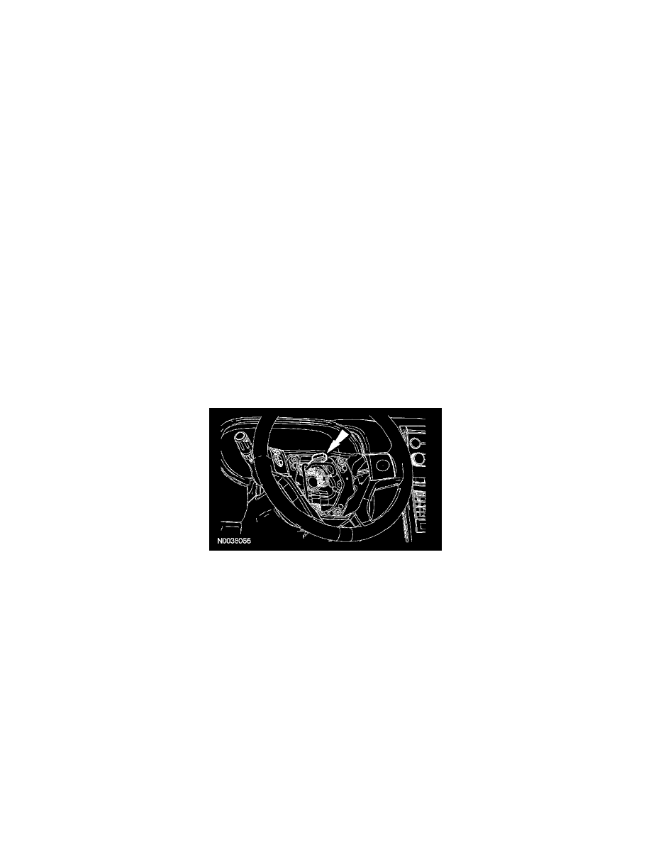
10. Remove the 2 screws and position aside the steering angle sensor.
11. Remove the 2 clockspring screws and remove the clockspring.
Installation
All vehicles
1. Install the clockspring and the 2 screws.
2. Position the steering angle sensor and install the 2 screws.
3. Connect the clockspring electrical connector.
4. Install the upper steering column shroud.
5. Install the lower steering column shroud and the 3 screws.
6. Install the I/P lower steering column opening cover and the 2 screws.
Vehicles installing a new clockspring
7. Install the steering wheel.
-
After the steering wheel installation, remove the clockspring sealing key.
Vehicle repairs reusing the same clockspring