
Explorer Sport Trac 4WD V6-4.0L VIN E (2007)
the RCM mounting is restored to its original condition.
-
Vehicle sensor orientation is critical for correct system operation. If a vehicle equipped with an air bag supplemental restraint system (SRS) is
involved in a collision, inspect the sensor mounting bracket and wiring pigtail for deformation. Install a new sensor and correctly position the
sensor or any other damaged SRS components whether or not the air bag is deployed.
-
The tightening torque of the air bag RCM retaining nuts is critical for correct system operation.
-
To reduce the risk of personal injury, do not use any memory saver devices.
CAUTION:
-
Electronic modules are sensitive to static electrical charges. If exposed to these charges, damage can result.
-
When installing a new RCM on vehicles built 7/31/06 or after, it is necessary to carry out programmable module installation (PMI). See:
Powertrain Management/Computers and Control Systems/Information Bus/Testing and Inspection/Programming and Relearning
NOTE:
-
When installing a new RCM, always make sure the correct RCM is being installed. If an incorrect RCM is installed, erroneous DTCs will result.
-
The air bag warning lamp illuminates when the RCM fuse is removed and the ignition switch is ON. This is normal operation and does not indicate
a SRS fault.
-
The SRS must be fully operational and free of faults before releasing the vehicle to the customer.
-
Repair is made by installing a new part only. If the new part does not correct the condition, install the original part and carry out the diagnostic
procedure again.
Vehicles built 7/31/06 or after
1. Carry out the steps necessary to prepare for programmable module installation (PMI).
All vehicles
2. Depower the system.
3. Remove the floor console.
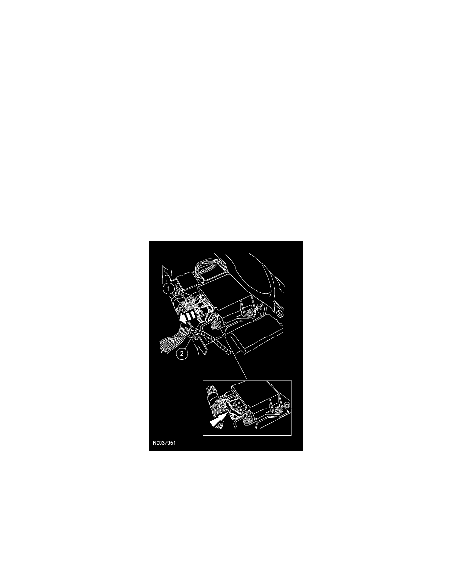
4. Disconnect the large restraints control module (RCM) electrical connector.
1
Pinch the thumb tab and pivot the large RCM electrical connector position assurance lever all the way back until it stops.
2
Pull out and disconnect the large RCM electrical connector.
5. Press to release the locking tab and disconnect the small RCM electrical connector.
6. Remove the 3 RCM nuts.
7. Remove the RCM.
Installation
All vehicles
1. Install the RCM.