
Explorer Sport Trac 4WD V6-4.0L VIN E (2007)
retention of these parts.
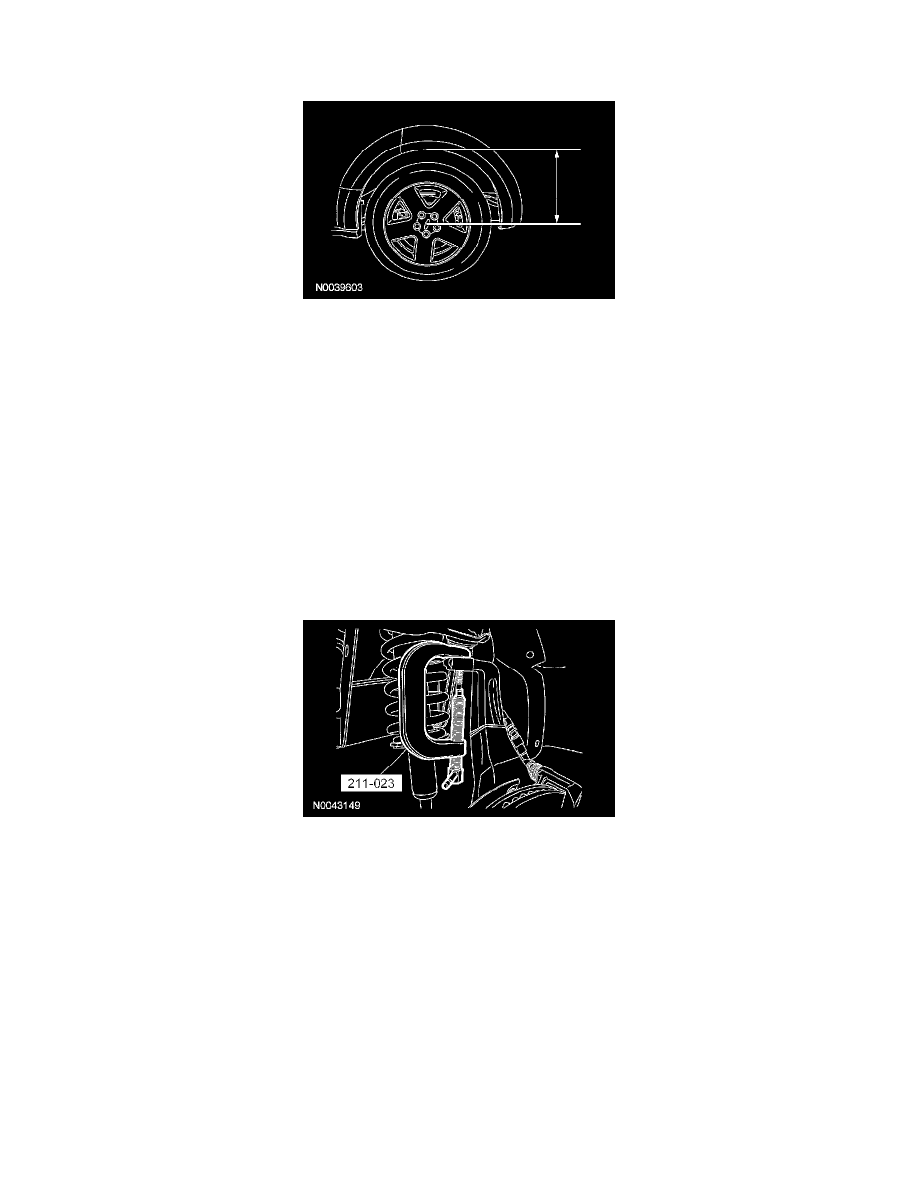
1. Measure the distance from the center of the hub to the lip of the fender with the vehicle in a level, static ground position (curb height).
2. Remove and discard the 3 shock absorber upper mount nuts.
^
To install, tighten to 30 Nm (22 ft. lbs.) at curb height.
3. With the vehicle in NEUTRAL, position it on a hoist. For additional information, refer to Maintenance/Service and Repair.
4. Using a suitable jack, support the lower control arm near the lower ball joint.
5. Remove and discard the stabilizer bar link nut and grommet and then remove the stabilizer bar link assembly.
^
To install, tighten to 35 Nm (26 ft. lbs.) at curb height.
6. Remove the shock absorber lower bolt and flag nut.
^
Discard the lower shock bolt and flag nut.
^
To install, tighten to 350 Nm (258 ft. lbs.) at curb height.
7. Remove and discard the upper ball joint nut.
^
To install, tighten to 55 Nm (41 ft. lbs.)
8. CAUTION: Do not use a hammer to separate the ball joint from the wheel knuckle or damage to the wheel knuckle can result.
CAUTION: Do not damage the ball joint boot while installing the special tool.
Using the special tool, separate the upper ball joint from the wheel knuckle.
9. While lowering the suspension, remove the shock and spring assembly.
10. CAUTION: Before tightening any suspension bushing fasteners, use a suitable jack to raise the suspension until the distance between the
center of the hub and the lip of the fender is equal to the measurement taken in Step 1 (curb height).
To install, reverse the removal procedure.
Rear Suspension
Shock Absorber and Spring Assembly