
Explorer Sport Trac 4WD V6-4.0L VIN K Flex Fuel (2004)
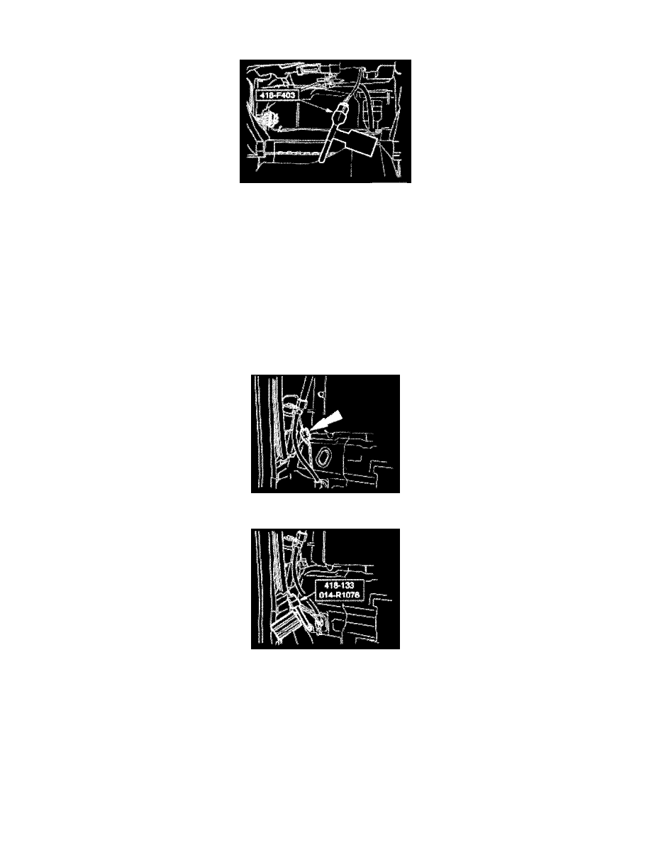
12. Disconnect the passenger air bag module electrical connector.
13. Attach the restraint system diagnostic tool to the vehicle harness side of the passenger air bag electrical connector.
Sport Trac vehicles without safety canopies
14. NOTE: Do not deactivate the safety canopy module circuit by removing the safety canopy bridge resistor from the safety canopy electrical
connector.
If the safety canopy bridge resistor is removed, an open circuit fault will be generated by the restraints control module (RCM).
If a restraint system diagnostic tool is installed at the safety canopy electrical connector, a low resistance fault will be generated by the RCM.
Sport Trac vehicles with safety canopies
15. Remove the passenger side C-pillar trim panel. For additional information, See: Body and Frame/Interior Moulding / Trim
16. Disconnect the passenger side safety canopy electrical connector.
17. Attach the restraint system diagnostic tool to the vehicle harness side of the passenger side safety canopy electrical connector.
18. Remove the driver side C-pillar trim panel. For additional information, See: Body and Frame/Interior Moulding / Trim