
Explorer Sport Trac 4WD V8-4.6L (2008)
1. Turn all vehicle accessories OFF.
2. Turn the ignition switch to OFF.
3. At the smart junction box (SJB), located below the LH side of the instrument panel, remove the cover and the restraints control module (RCM)
fuse 17 (10A) from the SJB.
4. Turn the ignition ON and visually monitor the air bag warning indicator for at least 30 seconds. The air bag warning indicator will remain lit
continuously (no flashing) if the correct RCM fuse has been removed. If the air bag warning indicator does not remain lit continuously, remove the
correct RCM fuse before proceeding.
5. Turn the ignition OFF.
6. WARNING: Always deplete the backup power supply before repairing or installing any new front or side air bag supplemental restraint
system (SRS) component and before servicing, removing, installing, adjusting or striking components near the front or side impact
sensors or the restraints control module (RCM). Nearby components include doors, instrument panel, console, door latches, strikers, seats
and hood latches.
Refer to the Description and Operation portion of Air Bag Systems for location of the RCM and impact sensor(s).
To deplete the backup power supply energy, disconnect the battery ground cable and wait at least 1 minute. Be sure to disconnect
auxiliary batteries and power supplies (if equipped).
Failure to follow these instructions may result in serious personal injury or death in the event of an accidental deployment.
Disconnect the battery ground cable and wait at least one minute.
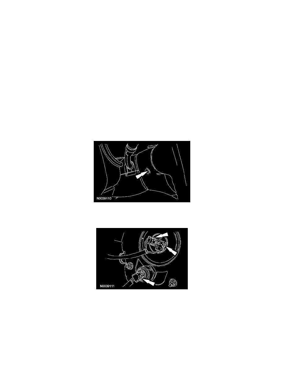
7. Remove the 2 driver air bag module bolts (1 shown).
8. NOTE: Note the position of the 3 driver air bag module wiring connectors for installation.
Disconnect the 3 driver air bag module electrical connectors and remove the driver air bag module.
9. Attach the restraint system diagnostic tools to the clockspring electrical connectors at the top of the steering column.