
Explorer Sport Trac 4WD V8-4.6L (2008)
3. Install the outer manual lever.
^
Tighten to 48 Nm (35 lb-ft).
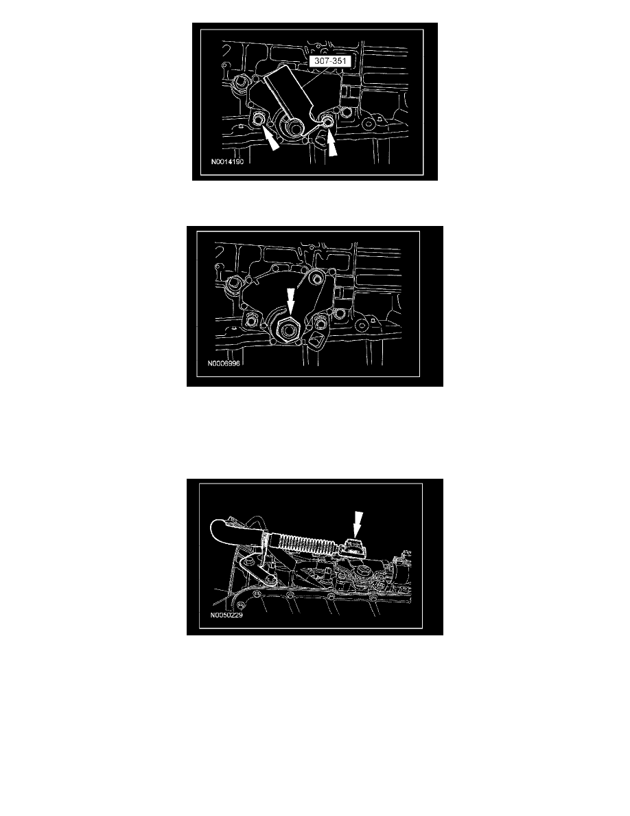
4. NOTE: When installing the selector lever cable, make sure that the selector lever cable locking tabs are locked in place and the selector lever
cable end is snapped onto the ball stud. Press the selector lever cable into the bracket and listen for the selector lever cable to click in place. Pull
back on the selector lever cable to make sure that it is locked into the selector lever cable bracket. Also make sure that the selector lever cable end
is correctly installed onto the ball stud. Pull back on the selector lever cable end to make sure that the selector lever cable end is correctly installed.
Install the selector lever cable to the manual control lever.
5. Connect the digital TR sensor electrical connector.