
Explorer Sport Trac 4WD V8-4.6L VIN 8 (2007)
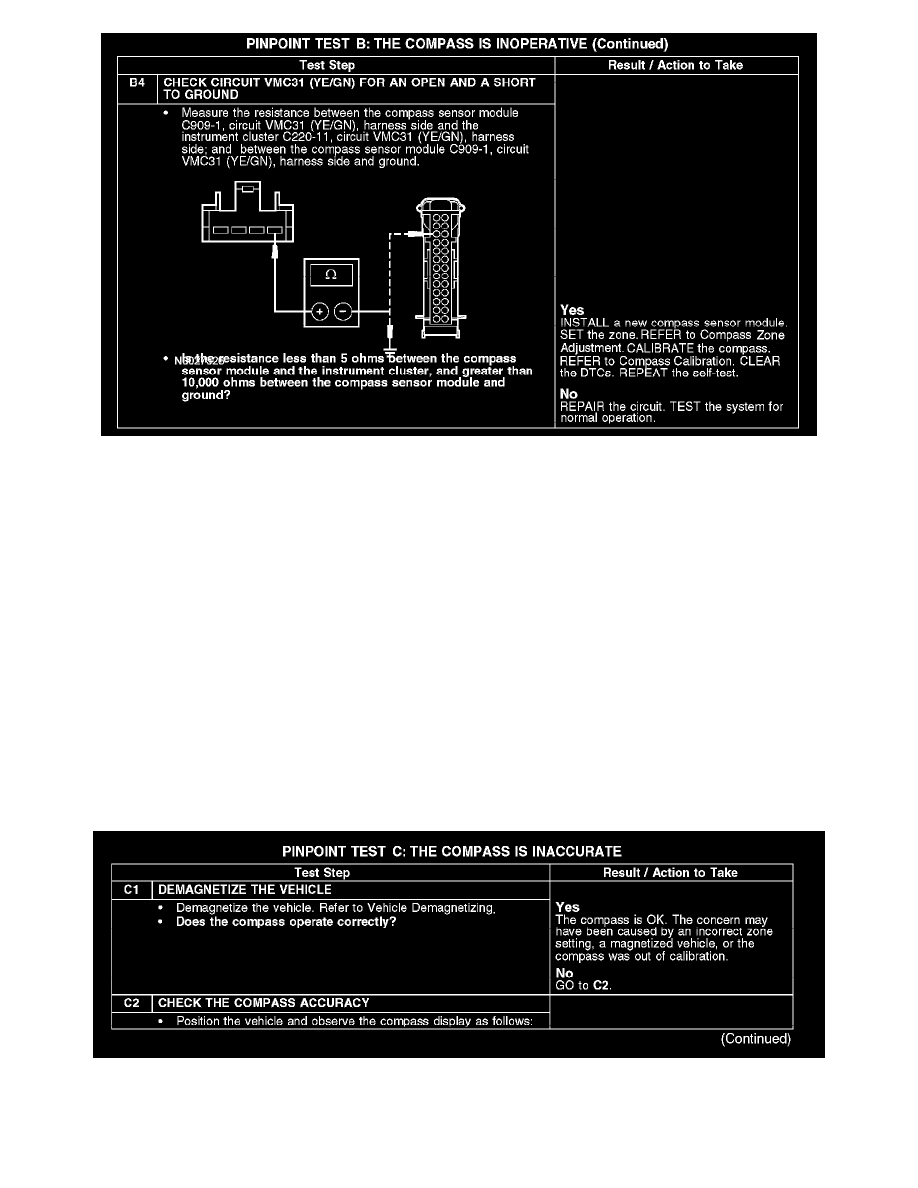
B4
Normal Operation
The compass sensor module receives voltage from the smart junction box (SJB) through circuit CBP18 (GY/OG) and is grounded through circuit
GD143 (BK/VT). The compass sensor module communicates the vehicle direction to the instrument cluster, which is displayed in the message center.
The compass sensor module uses circuits VMC30 (BU/GY) and VMC31 (YE/GN) to communicate to the instrument cluster.
DTC B2097 - is a continuous memory DTC that sets in the instrument cluster if the data received from the compass module is invalid.
DTC U2013 - is a continuous and on-demand DTC that sets if the instrument cluster fails to receive a response from the compass module after 4
consecutive attempts.
Possible Causes
-
Fuse
-
Circuit CBP18 (GY/OG) open
-
Circuit GD143 (BK/VT) open
-
Circuit VMC30 (BU/GY) open or short to ground
-
Circuit VMC31 (YE/GN) open or short to ground
--
Compass sensor module
Test C: The Compass Is Inaccurate
PINPOINT TEST C: THE COMPASS IS INACCURATE
C1-C2