
Explorer Sport Trac 4WD V8-4.6L VIN 8 (2007)
C3-C4
Normal Operation
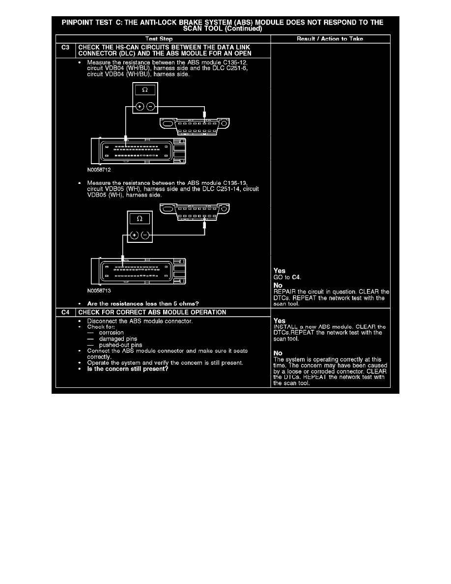
The ABS module communicates with the scan tool through the high speed controller area network (HS-CAN). Circuits VDB04 (WH/BU) (HS-CAN
+) and VDB05 (WH) (HS-CAN -) provide the network connection to the ABS module. The ABS module shares the HS-CAN network with the
powertrain control module (PCM), the transmission control module (TCM) (if equipped), the restraints control module (RCM), the four wheel drive
(4WD) control module (if equipped), the occupant classification sensor module and the instrument cluster. Voltage for the ABS module is provided by
circuits CBP18 (GY/OG), SBB06 (BN/RD) and SBB33 (RD). Ground is provided by circuit GD120 (BK/GN).
Possible Causes
-
Fuse
-
Circuit CBP18 (GY/OG) open
-
Circuit SBB06 (BN/RD) open
-
Circuit SBB33 (RD) open
-
Circuit GD120 (BK/GN) open
-
Circuit VDB04 (WH/BU) open (HS-CAN +)
-
Circuit VDB05 (WH) open (HS-CAN -)
-
ABS module