
1982 F 100 2WD Pickup L6-300 49L VIN E 1-bbl Steering and Suspension Alignment Information
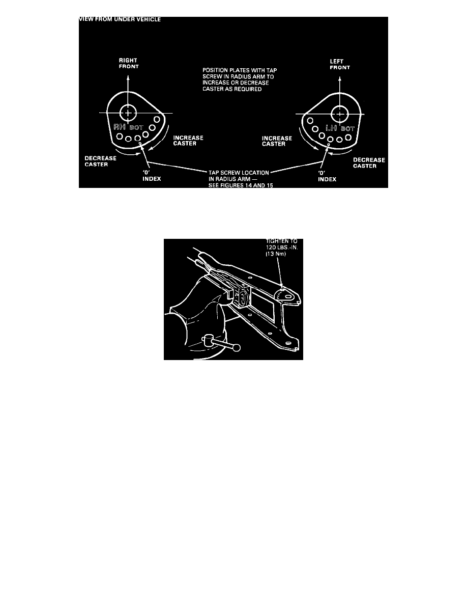
Figure 13 - Article 87-4-16
4.
Use a No. 6 drill to make a .204 inch diameter through hole at the punch mark. Line up the caster adjuster plate on the radius arm to obtain the
required change in caster, see Figure 13.
Figure 17 - Article 87-4-16
NOTE:
Each hole changes caster approximately 1/2 degree + or - from the "0" index hole.
5.
Install the tap screw to 120 in.lbs. (13 N-m) torque.
6.
Reinstall radius arm with a new bracket (front axle to radius arm). The new bracket has a larger "jaw" spacing to fit over caster adjuster plate.
^
For non-quad shock vehicles, install bracket E7TZ-3B446-A.
^
For quad shock vehicles, install bracket E7TZ-18112-A, R.H. or E7TZ-18113-A, L.H.