F 150 2WD V8-4.6L VIN 8 (2009)

E3-E4
Pinpoint Test F: The 4X4 Control Module Does Not Respond To The Scan Tool
Communications Network
Pinpoint Test F: The 4X4 Control Module Does Not Respond To The Scan Tool
Refer to Wiring Diagram Set 14, Module Communications Network for schematic and connector information. See: Diagrams/Electrical
Diagrams/Diagrams By Number
Refer to Wiring Diagram Set 34, All Wheel Drive (AWD) for schematic and connector information. See: Diagrams/Electrical Diagrams/Diagrams By
Number
Normal Operation
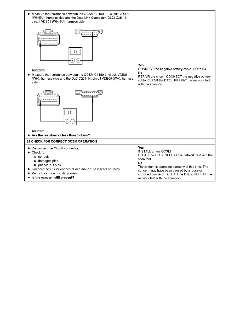
The 4X4 control module communicates with the scan tool through the High Speed Controller Area Network (HS-CAN). Circuits VDB04 (WH/BU)
(HS-CAN +) and VDB05 (WH) (HS-CAN -) provide the network connection to the 4X4 control module. Voltage is supplied by circuits CBB54
(VT/OG) and SBB68 (GN/RD). Ground is supplied by circuit GD123 (BK/GY).
This pinpoint test is intended to diagnose the following:
-
Fuse
