
F 150 2WD V8-4.6L VIN 8 (2009)
Air Bag(s) Arming and Disarming: Service and Repair
Reactivation
Supplemental Restraint System (SRS) Deactivation and Reactivation
Reactivation
1. Remove RCM fuse 31 (10A) from the SJB.
2. Disconnect the battery ground cable and wait at least one minute.
3. Connect the LH side safety canopy module electrical connector.
4. For regular cab, install the LH side B-pillar trim panel. For SuperCab and Crew Cab, install the LH side C-pillar trim panel.
5. Connect the RH side safety canopy module electrical connector.
6. For regular cab, install the RH side B-pillar trim panel. For SuperCab and Crew Cab, install the RH side C-pillar trim panel.
7. Under the driver seat, connect inline electrical connector C339, slide and engage the locking clip.
8. Under the driver seat, connect inline electrical connector C3051, slide and engage the locking clip.
9. Connect the 2 passenger air bag module electrical connectors.
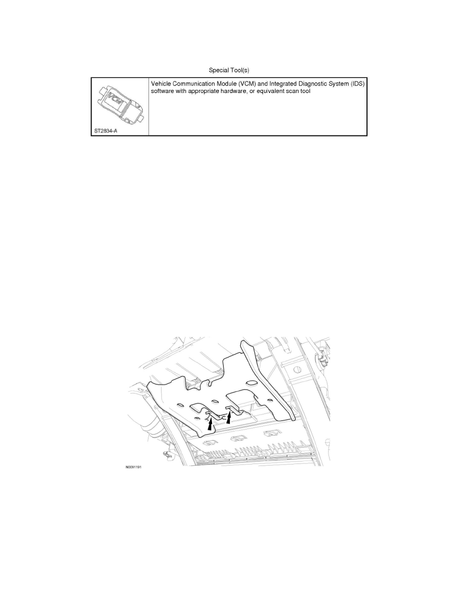
10. Position the passenger air bag module so that the tabs are oriented as shown.
11. Install the 3 passenger air bag module bolts.
-
Tighten to 8 Nm (71 lb-in).
12. Install the driver air bag module. Refer to Driver Air Bag Module See: Air Bag/Service and Repair/Driver Air Bag Module.
13. Turn the ignition from OFF to ON.
14. Install RCM fuse 31 (10A) to the SJB and install the cover.
15. WARNING: Make sure no one is in the vehicle and there is nothing blocking or placed in front of any air bag module when the battery is
connected. Failure to follow these instructions may result in serious personal injury in the event of an accidental deployment.