F 150 2WD V8-4.6L VIN W (2007)

F3-F5
Normal Operation
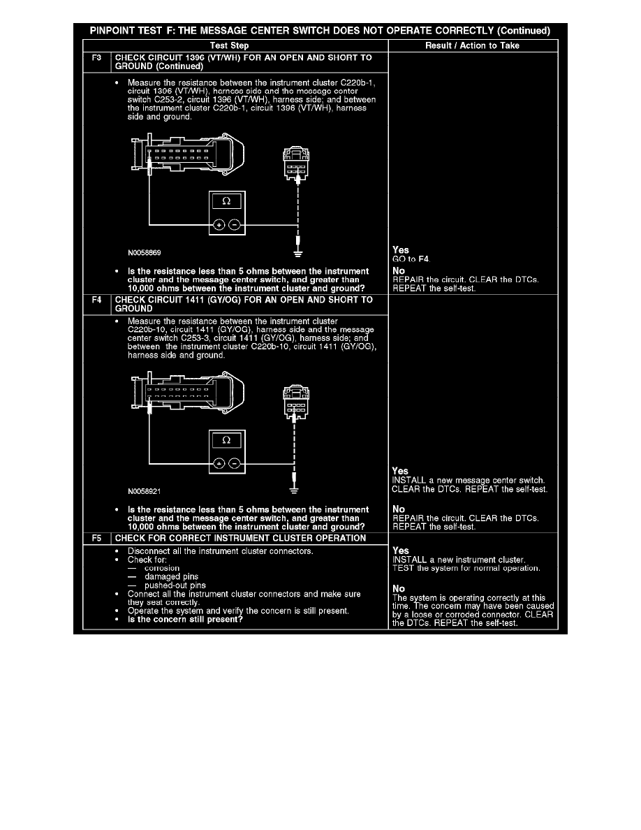
The message center functionality is controlled through the message center switch, which is hardwired to the instrument cluster through the input circuit
1411 (GY/OG) and the return circuit 1396 (VT/WH). There are 3 message center switch buttons with each button operating a switch that uses
different resistance values. The instrument cluster sends out a reference voltage to the message center switch on the input circuit and monitors the
voltage drop when a message center switch button is pressed. The voltage drop will vary depending upon the resistance of each button, providing a
specific indication to the instrument cluster which switch is pressed.
DTC B1209 - sets on-demand in the instrument cluster if any of the buttons on the message center are stuck or pressed during the self-test.
Possible Causes
-
Circuit 1396 (VT/WH) open or short to ground
