
F 150 2WD V8-4.6L VIN W (2007)
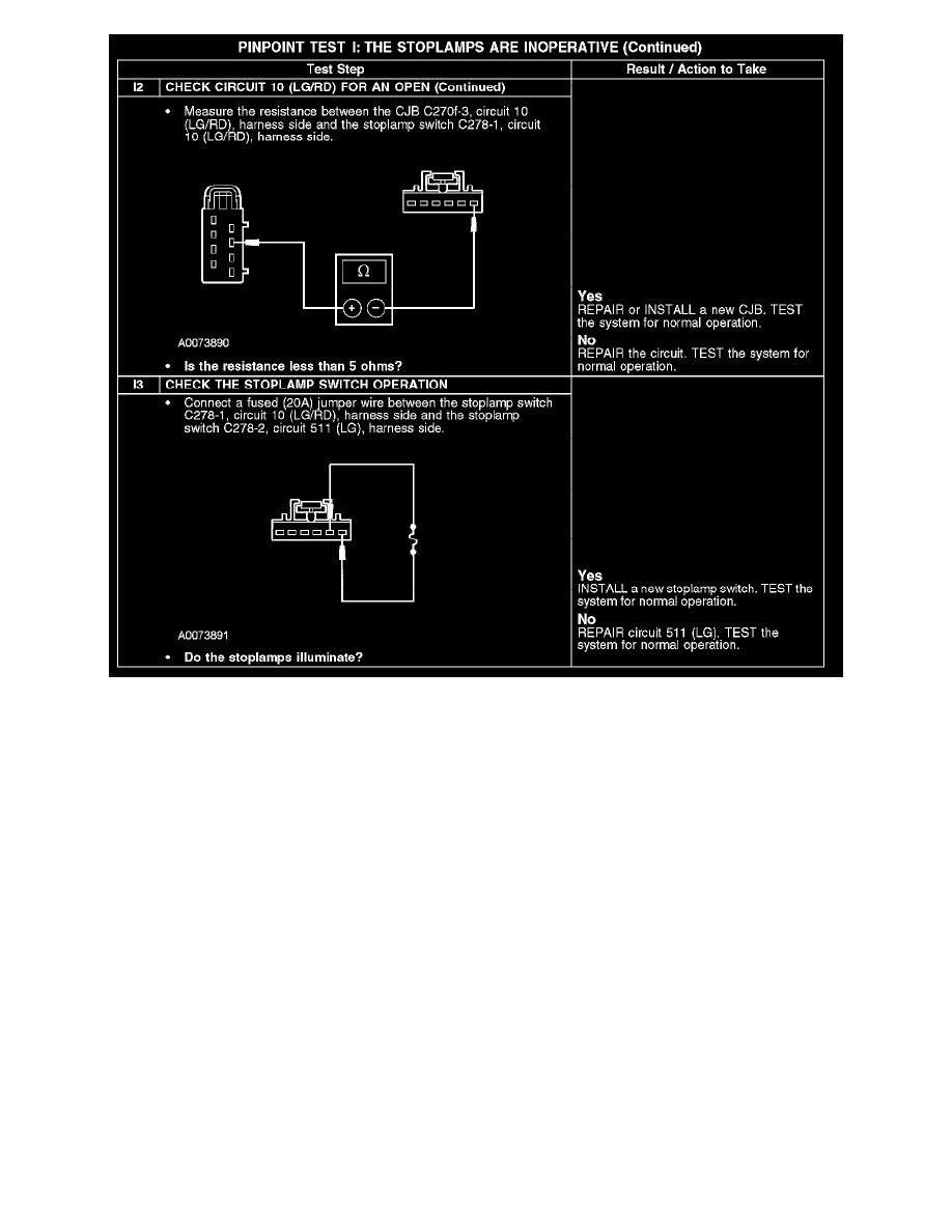
I2-I3
Normal Operation
The stoplamp switch is supplied battery voltage through circuit 10 (LG/RD). When the brake pedal is applied, the stoplamp switch routes voltage to
circuit 511 (LG). Circuit 511 (LG) supplies voltage to the multifunction switch and the high mounted stoplamp. The multifunction switch internally
routes the power (when in the NEUTRAL position) to circuits 9 (LG/OG) (LH stoplamp) and 5 (OG/LB) (RH stoplamp). Circuits 9 (LG/OG) and 5
(OG/LB) are routed to the central junction box (CJB) fuses 36 and 42 and then to the LH and RH stoplamps, accordingly.
Possible Causes
-
Fuse
-
Circuit 10 (LG/RD) open
-
Circuit 511 (LG) open
-
Stoplamp switch
-
CJB
Test J: One or More Stoplamps Are Inoperative
PINPOINT TEST J: ONE OR MORE STOPLAMPS ARE INOPERATIVE