
F 150 2WD V8-5.4L Flex Fuel (2008)
15. Remove the 3 bolts and the 3 accessory drive idler pulleys.
16. Remove the 4 bolts and the coolant pump pulley.
17. Remove the 3 bolts and the accessory drive belt tensioner.
18. Disconnect the RH camshaft position (CMP) sensor electrical connector.
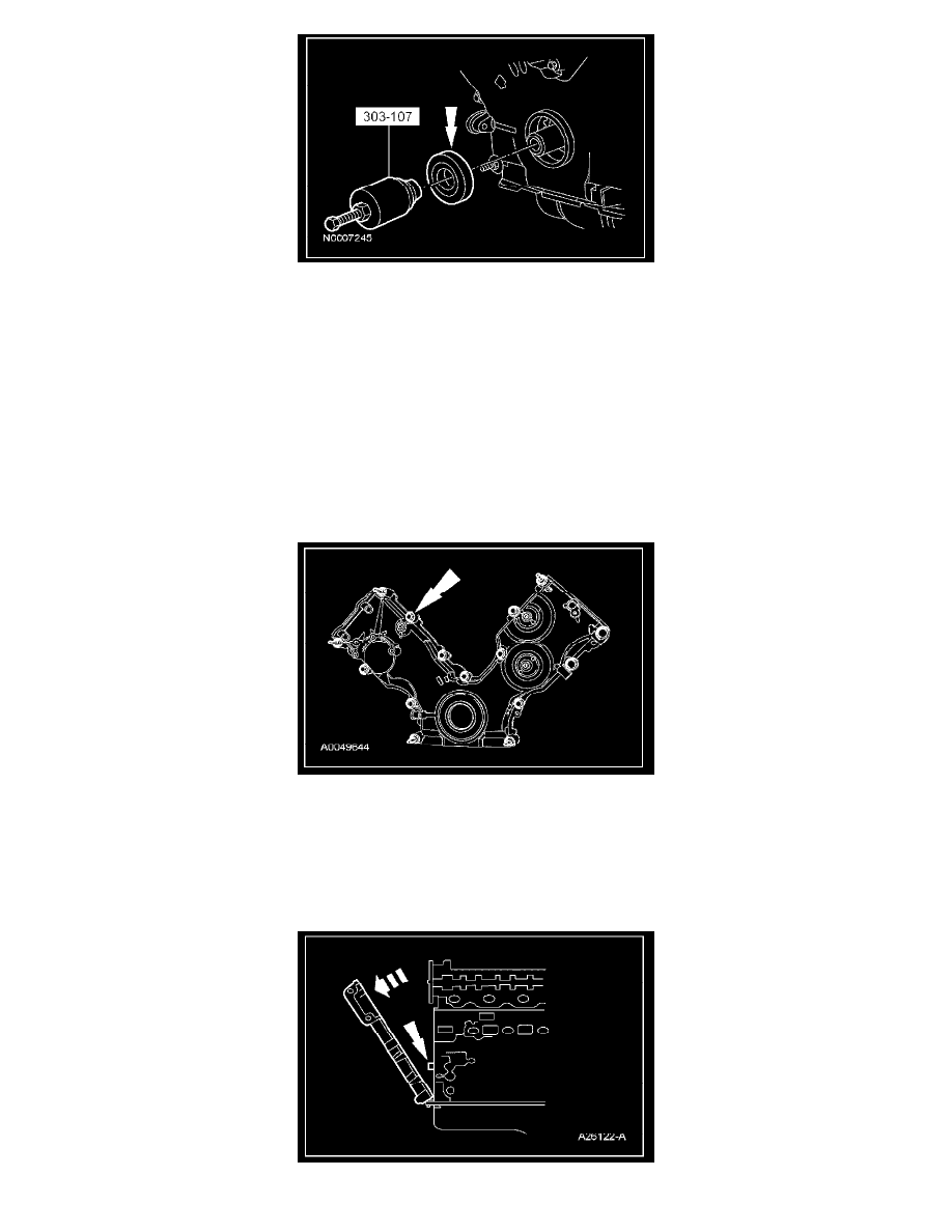
19. Remove the bolt and the RH CMP sensor.
^
Discard the O-ring seal.
20. Remove the nut and position the RH radio ignition interference capacitor aside.
21. Disconnect the LH CMP sensor electrical connector.
22. Remove the bolt and the LH CMP sensor.
^
Discard the O-ring seal.
23. Remove the nut and position the LH radio ignition interference capacitor aside.
24. Disconnect the crankshaft position (CKP) sensor electrical connector.
25. Remove the 4 front oil pan bolts.
26. Remove the bolts and the studs.
27. CAUTION: Do not use metal scrapers, wire brushes, power abrasive discs or other abrasive means to clean the sealing surfaces. These
tools cause scratches and gouges which make leak paths. Use a plastic scraping tool to remove all traces of old sealant.
Remove the engine front cover from the front cover to cylinder block dowel.
^
Remove the engine front cover gaskets.
^
Clean the mating surfaces with silicone gasket remover and metal surface prep. Follow the directions on the packaging.
^
Inspect the mating surfaces.