
F 150 2WD Pickup V8-5.4L SOHC VIN 3 (1999)
General Module: Description and Operation
NOTE
-
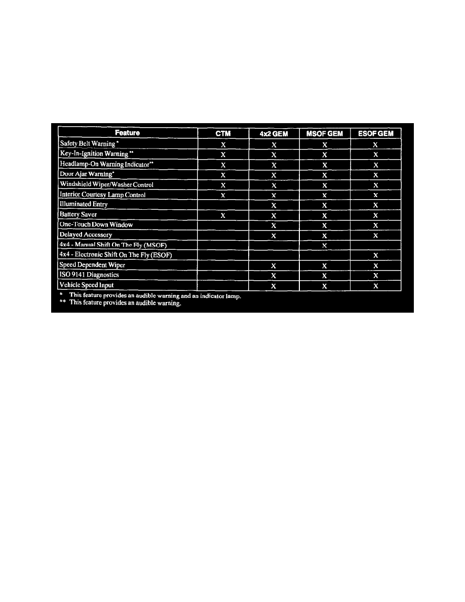
Each vehicle has either a Generic Electronic Module (GEM) or Central Timer Module (CTM). The difference in functionality is defined in the
GEM/CTM Feature Matrix.
-
The GEM/CTM inputs and outputs are designed to withstand continuous exposure to a short circuit to ground or battery voltage without being
damaged.
The multifunction modules consist of the following:
-
Remote Anti-Theft Personality (RAP) module
-
Central Timer Module (CTM) with diagnostic connector
-
Generic Electronic Module (GEM)
GEM/CTM Feature Matrix
Ignition Switch Positions
The position of the ignition switch is very important to proper GEM/CTM operation. Often times, erratic or unexpected operation can be traced to
problems on these GEM/CTM inputs. The following is a brief description of five ignition switch positions.
When the ignition switch is in the RUN position, battery voltage should be present at the GEM/CTM RUN and RUN/ACC input terminals.
When the ignition switch is in the ACC position, battery voltage should be present at the GEM/CTM RUN/ACC input terminal only.
When the ignition switch is in the START position, battery voltage should be present at the GEM/CTM start/clutch depressed input.
The GEM module does not have an OFF or LOCK switch state input. The GEM will assume the OFF or LOCK position when there are no RUN,
ACC, or START signals present.