
F 150 4WD V8-4.6L VIN 8 (2010)
Yes
GO to AE6.
No
VERIFY the BJB fuse 17 (30A) is OK. If OK, REPAIR circuit SBB17 (RD) for an open. TEST the system for normal operation. If not OK, REFER to
the Wiring Diagrams to identify the possible causes of the circuit short. See: Diagrams/Electrical Diagrams/Diagrams By Number
-------------------------------------------------
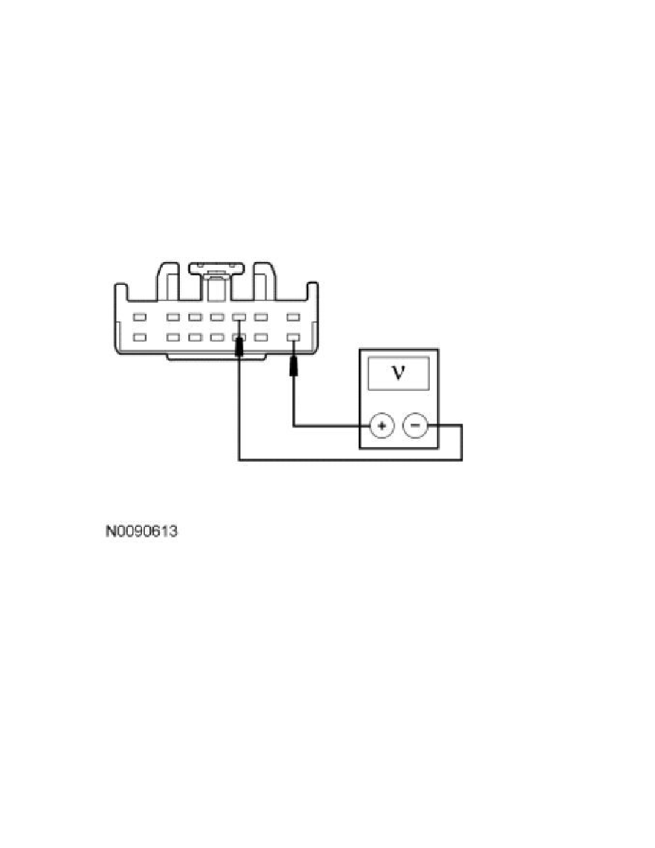
AE6 CHECK FOR VOLTAGE TO THE TBC MODULE USING THE CONNECTOR GROUND
-
Measure the voltage between the TBC module C2142-8, circuit SBB17 (RD), harness side and the TBC module C2142-3, circuit GD138
(BK/WH), harness side.
-
Is the voltage greater than 10 volts?
Yes
GO to AE7.
No
REPAIR circuit GD138 (BK/WH) for an open. TEST the system for normal operation.
-------------------------------------------------
AE7 CHECK THE STOPLAMP SWITCH INPUT TO THE TBC MODULE
-
While applying the brake pedal, measure the voltage between the TBC module C2142-12, circuit CBB82 (GN), harness side and ground.