
F 150 4WD V8-4.6L VIN 8 (2010)
The memory driver seat feature allows the driver to program a personalized seat position that can be recalled using the memory switches. Refer to Seats.
The adjustable pedals are also controlled by the DSM. This system permits the adjustment of the brake and accelerator pedals using the adjustable pedal
switch. Refer to Hydraulic System, Brakes &/or Brake Pedal Assy.
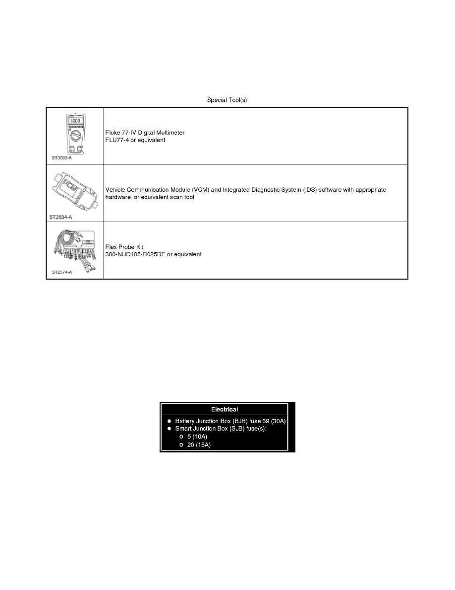
Special Tools Used With Diagnostics
Driver Seat Module (DSM)
Inspection and Verification
Smart Junction Box (SJB)
Inspection and Verification
1. Verify the customer concern.
2. Visually inspect for obvious signs of electrical damage.
Visual Inspection Chart
3. If an obvious cause for an observed or reported concern is found, correct the cause (if possible) before proceeding to the next step.
4. NOTE: Make sure to use the latest scan tool software release.
If the cause is not visually evident, connect the scan tool to the Data Link Connector (DLC).
5. NOTE: The Vehicle Communication Module (VCM) LED prove-out confirms power and ground from the DLC are provided to the VCM.
If the scan tool does not communicate with the VCM:
-
Check the VCM connection to the vehicle.
-
Check the scan tool connection to the VCM.