
F 150 4WD V8-4.6L VIN 8 (2010)
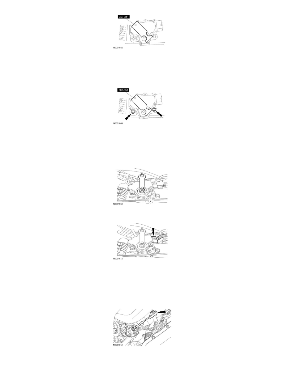
3. NOTICE: Tightening one bolt before tightening the other may cause the sensor to bind or become damaged.
Tighten the bolts in an alternating sequence.
-
Tighten to 9 Nm (80 lb-in).
4. Install the manual control lever.
1. Position the manual control lever.
2. Install a new manual control lever outer nut.
-
Tighten to 33 Nm (24 lb-ft).
5. Connect the TR sensor connector.
6. NOTICE: To prevent selector lever cable damage, do not apply force to the selector lever cable between the manual control lever and the
selector lever cable bracket.
NOTE: When installing the selector lever cable end, make sure that the selector lever cable end is correctly installed onto the manual control
lever. Pull back on the selector lever cable end to make sure that the selector lever cable end is correctly installed onto the manual control lever.
Connect the selector lever cable end to the manual control lever with the lever in the (D) position.