
F 150 4WD V8-4.6L VIN 8 (2010)
-
Is the battery voltage between 13-15.2 volts?
Yes
For DTC B1318, GO to B4.
For DTC B1317, GO to B6.
No
REFER to Charging System to diagnose the charging system. CLEAR all CMDTCs. TEST the system for normal operation.
-------------------------------------------------
B4 CHECK THE VOLTAGE TO THE TBC MODULE
-
Ignition OFF.
-
Disconnect: TBC Module C2142.
-
Ignition ON.
-
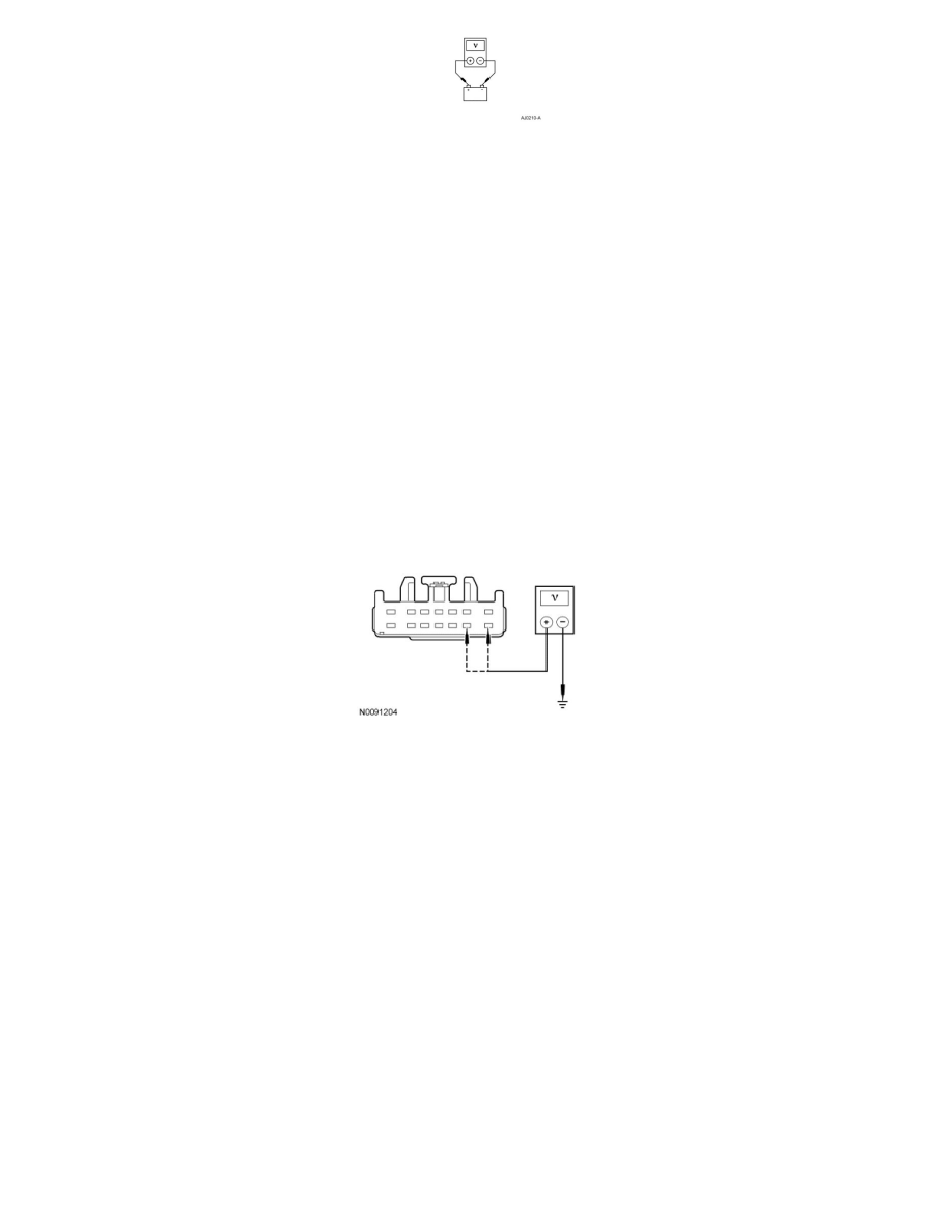
Measure the voltage between ground and:
-
TBC module C2142-8, circuit SBB17 (RD), harness side.
-
TBC module C2142-9, circuit CBP33 (WH/BN), harness side.
-
Are the voltages greater than 10 volts?
Yes
GO to B5.
No
VERIFY BJB fuse 17 (30A) is OK. If OK, REPAIR circuit SBB17 (RD).
VERIFY SJB fuse 33 (10A) is OK. If OK, REPAIR circuit CBP33 (WH/BN).
If either fuse is not OK, REFER to the Wiring Diagrams to identify the possible causes of the circuit short. See: Diagrams/Electrical Diagrams/Diagrams
By Number
CLEAR the DTCs. REPEAT the self-test.
-------------------------------------------------
B5 CHECK THE TBC MODULE GROUND CIRCUIT FOR AN OPEN
-
Ignition OFF.
-
Measure the resistance between TBC module C2142-3, circuit GD138 (BK/WH), harness side and ground.