
F 150 4WD V8-4.6L VIN 8 (2010)
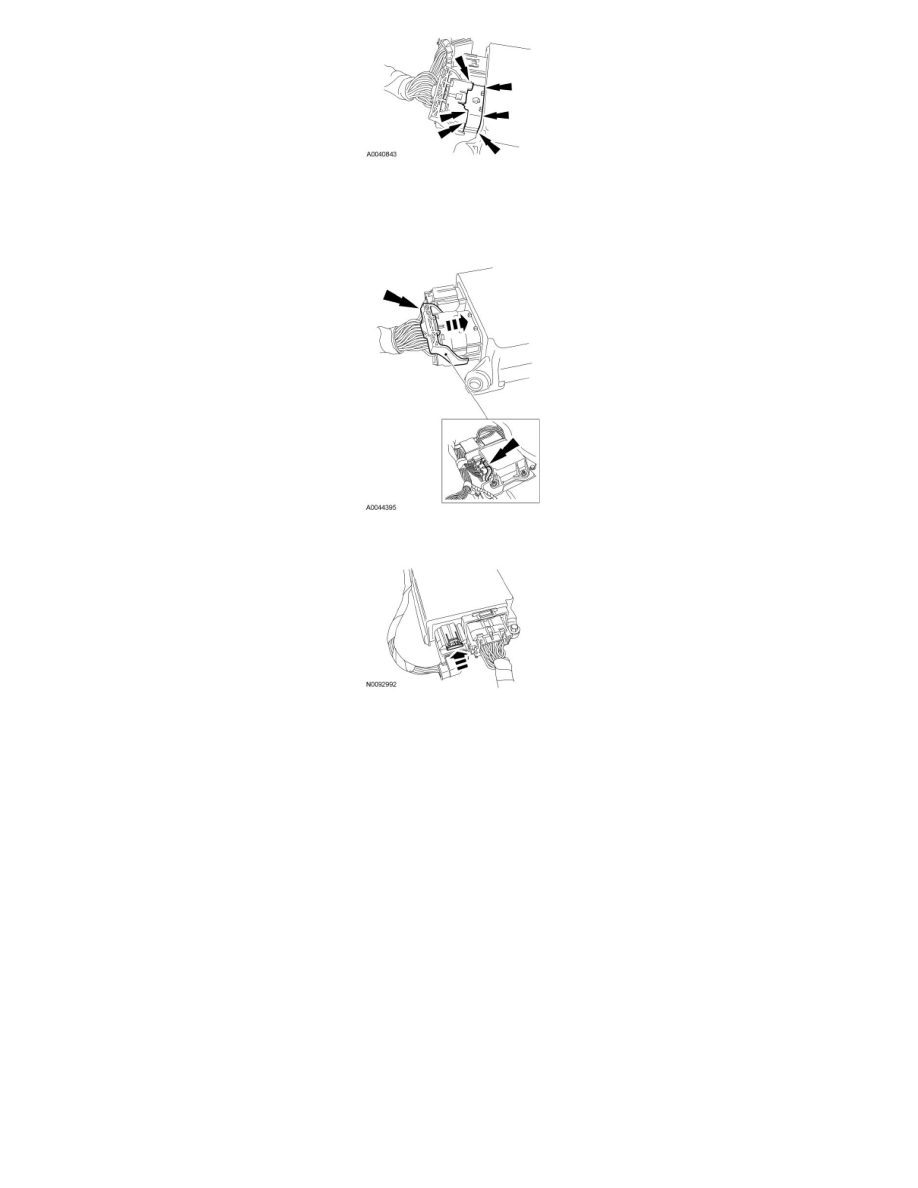
4. Connect the large RCM electrical connector.
-
Using the connector position assurance lever, pivot it toward the RCM, drawing the connector into the RCM.
-
Make sure the thumb tab is engaged to the retainer on the RCM and locked in place.
5. Connect the small RCM electrical connector and push the lock tab in.
6. If equipped, install the floor console. For additional information, refer to Instrument Cluster / Carrier &/or Interior Moulding / Trim.
7. If equipped, install the front center seat cushion and cupholder assembly. For additional information, refer to Seats.
8. Repower the SRS. For additional information, refer to Supplemental Restraint System (SRS) Depowering and Repowering See: Body and
Frame/Interior Moulding / Trim/Dashboard / Instrument Panel/Air Bag(s) Arming and Disarming/Service and Repair/Supplemental Restraint
System (SRS) Depowering and Repowering.
9. If a new RCM was installed, carry out the appropriate steps to complete the Programmable Module Installation (PMI) procedure. For additional
information, refer to Information Bus. See: Powertrain Management/Computers and Control Systems/Information Bus/Testing and
Inspection/Programming and Relearning